
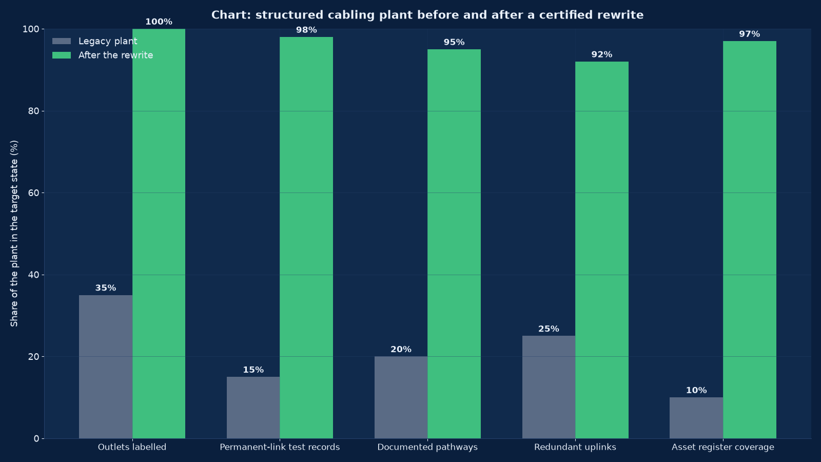
Chart values are an illustrative planning model based on typical UMC engagements and published industry benchmarks. They are not a guarantee of results on any specific project.
A cabling plant has a fifteen-year service life and a two-year memory. The people who knew what every cable did have left, the drawings were never updated, and the plant now runs on institutional guesswork. The fix is not tidier cable management. It is labelling, testing and documentation to a standard that survives the departure of the person who wrote it — because that person will leave too.
Structured cabling, LAN and WAN engineering at Unified Management Consulting is the physical and data-link layer of an enterprise network, designed and certified rather than installed and assumed. It is the horizontal copper and fibre, the pathways and containment, the telecommunications rooms and their power and cooling, the switching hierarchy that connects them, and the WAN handoff where the building meets the carrier. It is also the paperwork: a labelling scheme that survives a decade, permanent-link test records for every outlet, as-built drawings that match what is actually in the ceiling, and an asset register someone can query at two in the morning.
This work is unfashionable and consequential. Every other network discipline — wireless, security, software-defined WAN, unified communications, monitoring — sits on top of it and inherits its defects. A Wi-Fi deployment onto a plant whose access switches cannot deliver the power budget produces access points running at reduced radio capability, and the survey will show coverage that does not exist. A segmentation programme onto a plant with undocumented VLANs and no redundant uplinks produces a design that cannot be implemented without an outage. We are usually called after one of those has happened.
🔌 Structured Cabling, LAN & WAN Engineering — Quick Summary
| Component | What We Deliver |
|---|---|
| Plant survey and audit | Every outlet, pathway, room and uplink recorded, with a condition assessment, a test-record gap analysis and a written statement of what the plant can and cannot support. |
| Cabling design to standard | Horizontal and backbone design against the recognised standards, with the performance category justified by the workloads rather than chosen from a price list. |
| Pathways and containment | Tray, conduit, basket and riser routes sized for today plus growth, with separation from power and the fill ratio respected. |
| Telecommunications room design | Rack layout, power circuits, earthing and bonding, cooling load, lighting and access control — the things that decide whether a room survives its own equipment. |
| Copper and fibre media selection | Category choice per application, single-mode versus multimode fibre by distance and transceiver economics, and the mixed-media reality of most plants. |
| LAN switching hierarchy | Access, distribution and core roles, uplink capacity, stacking and redundancy, loop prevention and the Layer 2 topology designed rather than discovered. |
| Power over Ethernet budgeting | Per-port and per-switch power, the actual draw of the devices being powered, and the headroom for the access points and cameras of the next five years. |
| WAN handoff and carrier demarcation | Where the carrier’s responsibility ends, what the building’s plant has to provide, and the demarcation point documented. |
| Certification and testing | Permanent-link certification for copper, tier-one and tier-two testing for fibre, with records delivered in a queryable format. |
| Labelling and as-built documentation | A scheme applied consistently across outlets, patch panels, rooms and cores, with drawings and an asset register that can be maintained. |
| Remediation and re-termination programmes | Phased correction of an existing plant without taking the business off the network, usually floor by floor. |
The Plant Outlives the Equipment: Why Cabling Is an Engineering Decision
The reason to treat cabling as an engineering discipline rather than a trades activity is that it is the only part of the network with a service life longer than the equipment connected to it. Switches are replaced every five to seven years; access points every four to six; the cabling in the ceiling stays for fifteen or more. Whatever category you install today has to carry four generations of equipment that do not exist yet.
| Decision | Cheap answer | Engineered answer | What the difference costs later |
|---|---|---|---|
| Performance category | The lowest category that meets today’s requirement | The category that carries the next two generations of access-layer speed with margin | A full re-cable, at roughly three times the original cost, when 10 GbE reaches the desk |
| Pathway fill | Fill the tray to save a route | Fill to the standard ratio and leave the growth path documented | New cables pulled alongside an over-full tray, with bend radius and crosstalk both compromised |
| Room power and cooling | Plug the rack into the nearest socket | Dedicated circuits, redundant feeds, and cooling sized for the actual heat load | A room that trips at peak, or equipment that throttles in summer |
| Uplink redundancy | One uplink per access switch | Diverse redundant uplinks to diverse distribution switches | A single cable fault taking out a floor, and no way to fix it during business hours |
| Labelling | Handwritten tape at installation | A documented scheme applied to outlets, panels, cores and rooms, with a register | Every future fault diagnosed by elimination, which takes hours instead of minutes |
| Testing | A link-light check | Permanent-link certification with records for every outlet | Intermittent faults attributed to software for months, because nobody can prove the cable is good |
| Documentation | The contractor’s own drawings | As-builts that match the installed plant, in a format the client can maintain | A plant whose knowledge lives with one person, until they resign |
Notice that every row’s engineered answer costs more at installation and less over the plant’s life, and that the expensive failure is never the cable itself — it is the inability to prove what the cable does. That is why our deliverables weight labelling, test records and documentation as heavily as the physical installation.
Plant Survey and Audit: Turning Guesswork into a Known Quantity
A survey is not a walk-round with a clipboard. It is the process of converting an undocumented plant into a known quantity, and it has to produce something a designer can work from and an auditor can read.
| Survey activity | What it produces | Why it matters |
|---|---|---|
| Outlet count and location capture | A floor-by-floor inventory with positions | Establishes scale, and reveals outlets nobody knew existed — which are usually the ones carrying something important |
| Labelling state assessment | The share of outlets, panels and cores that are legibly and consistently labelled | Predicts how long every future fault diagnosis will take |
| Pathway and containment survey | Routes, sizes, fill levels and available growth paths | Decides whether new cable can be added at all, and where the bottlenecks are |
| Room condition assessment | Power circuits, cooling capacity, earthing, access control, lighting, dust | A room that fails here constrains everything that goes in it |
| Media and age identification | What category and fibre type is installed, and roughly when | Determines what the plant can support and what its remaining life is |
| Test-record gap analysis | Which links have certification records and which do not | The gap is the risk; an untested link is an unknown, not a working cable |
| Switching topology capture | What connects to what, on which ports, in which VLANs | Without it, Layer 2 design is guesswork and every change is dangerous |
| Fault history review | Recurring faults, workarounds and unresolved incidents | The plant’s symptom record, which usually points at a structural defect rather than bad luck |
| Written capability statement | A document saying what the plant can and cannot support | The sentence that stops an unrealistic project being approved |
The audit ends with a number, not an opinion
Every survey we deliver ends with a scored plant condition: outlets labelled, links with test records, pathways documented, uplinks redundant, asset register coverage. Those percentages are the baseline in Figure 1, and the reason they matter is that they make the remediation programme a quantified target rather than a general improvement. A plant at 35 per cent labelled and 15 per cent tested is not slightly untidy; it is structurally unmanageable, and the numbers say so in a way that survives a change of IT manager.
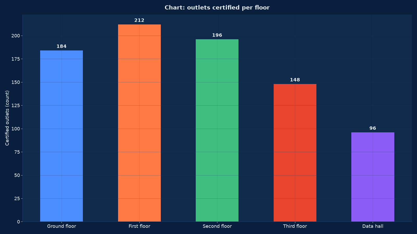
Chart values are an illustrative planning model based on typical UMC engagements and published industry benchmarks. They are not a guarantee of results on any specific project.
Media Selection: Copper Where It Is Cheap, Fibre Where It Is Necessary
Media selection is the decision with the longest consequences, because it is the one that cannot be revisited without opening the ceiling. The two questions are what the access layer has to carry and how far it has to carry it.
| Medium | Distance and speed reality | Cost position | Where it belongs | The trap |
|---|---|---|---|---|
| Cat6 copper | 1 GbE to 100 metres comfortably; 10 GbE only to short distances and only with careful installation | Lowest | Legacy plant, and low-speed access where the budget genuinely cannot stretch | Being asked to carry multi-gigabit access points, which it often cannot |
| Cat6A copper | 10 GbE to 100 metres, with the alien crosstalk performance to prove it | Moderate | The default access-layer medium for new builds and rewires | Installed without the bend radius and separation discipline the category assumes, which voids the performance |
| Multimode fibre | High speed over building-scale distances, with transceiver costs that suit short reach | Moderate cable, higher termination skill | Backbone within a building, room-to-room risers, and short data-hall links | Being chosen for long runs where single-mode would have been cheaper overall |
| Single-mode fibre | Very high speed over kilometres, with transceivers that have become inexpensive | Higher cable and termination cost, lower lifetime cost for long reach | Backbone between buildings, WAN handoff, and any run beyond multimode’s comfort | Being omitted from a design because the cable price looked high, then needed for a link the plant cannot carry |
| Direct-attach copper for in-rack | Short, cheap, low latency inside a rack | Lowest | Top-of-rack connections where the distance allows | Being used beyond its distance, which produces errors that look like a switch fault |
| Legacy and mixed media | Whatever is still in the ceiling from previous decades | Sunk | Nowhere — but it is there, and it has to be mapped | Being assumed to be the same category as its neighbours, which is how a migration fails half way |
Figure 3 shows what a real plant looks like once the design is deliberate rather than accidental: copper dominating the access edge where distances are short and cost per port matters, and single-mode fibre dominating the core and WAN handoff where distance and bandwidth do. The mistake we most often correct is a plant where the same medium was used everywhere because one contractor supplied it, which leaves either an expensive access layer or a core that cannot carry the traffic.
Pathways, Containment and the Room That Has to Hold It All
Pathways are the constraint that decides whether a plant can grow. Cable can always be pulled; whether there is anywhere to put it is a different question, and the answer is usually found after the project has been approved.
| Pathway element | Design rule | What happens when it is ignored |
|---|---|---|
| Tray and basket fill | Filled to the standard ratio with growth reserved | New cable forced into an over-full tray, with bend radius and airflow both compromised |
| Separation from power | Maintained separation from power cabling, with crossings at right angles | Alien crosstalk and induced noise that appear as intermittent errors under load |
| Bend radius | Respected for the cable type, at every turn and every entry point | Degraded performance that passes a link-light check and fails a certification test |
| Riser and backbone routes | Fire-stopped at every penetration, with capacity for the backbone’s growth | A fire-stopping defect found by an auditor, and a riser that cannot take another cable |
| Conduit and underfloor routes | Sized with draw-in capacity, and pull strings left in place | A route that exists on the drawing and cannot be used in practice |
| Service loops and slack | Left at both ends, managed rather than stuffed | Re-termination impossible without replacing the whole run |
| Containment earthing and bonding | Bonded per the standard, with records | Potential differences and interference, and a safety defect that is also a performance defect |
| Growth path documentation | Recorded as part of the as-built, including spare capacity per route | The next project commissioning a survey to find what the last project already knew |
We treat spare pathway capacity as a delivered asset rather than as an accident of installation, and we record it per route in the as-built documentation. It is one of the cheapest things to buy at installation time and one of the most expensive to retrofit, which is exactly the pattern of every other decision in this discipline.
The Telecommunications Room Is a Facility Problem
The telecommunications room is where cabling stops being a trades matter and becomes a facility engineering problem, because it contains powered equipment in a space that was usually designed as a store room. Its constraints are the ones that produce outages nobody can explain from the network side.
| Room element | Requirement | Failure it prevents |
|---|---|---|
| Dedicated power circuits | Circuits reserved for the room’s equipment, with capacity for growth and no sharing with other loads | A socket elsewhere in the building tripping a floor’s network |
| Redundant feeds where the room is critical | Two diverse supplies for rooms carrying distribution or core equipment | A single distribution fault taking out multiple floors |
| Cooling sized for the actual load | Heat load calculated from the installed and planned equipment, not estimated | Equipment throttling or failing in summer, presenting as random network degradation |
| Uninterruptible power for the room | Runtime sufficient for a controlled shutdown or generator start | A building power blip becoming a network outage |
| Earthing and bonding | A telecommunications bonding backbone with documented connections | Potential differences damaging equipment and degrading signal integrity |
| Rack layout and cable management | Space for switches, patching, slack management and airflow, with vertical and horizontal management | A rack that cannot be worked on without unplugging things |
| Access control and environmental monitoring | Restricted access, with temperature, humidity and water detection alarmed | An uncontrolled room, and a leak discovered by an outage rather than by a sensor |
| Lighting and working space | Adequate light and clearance to work safely | Poor workmanship, which shows up as faults months later |
This is also where the boundary with facility engineering has to be drawn explicitly. A cabling contractor cannot design a room’s cooling load or its power distribution, and a facility team cannot specify the containment and bonding the network needs. We hold both sides in one design, which is why our data centre and facility work sits alongside this offering rather than separately from it.
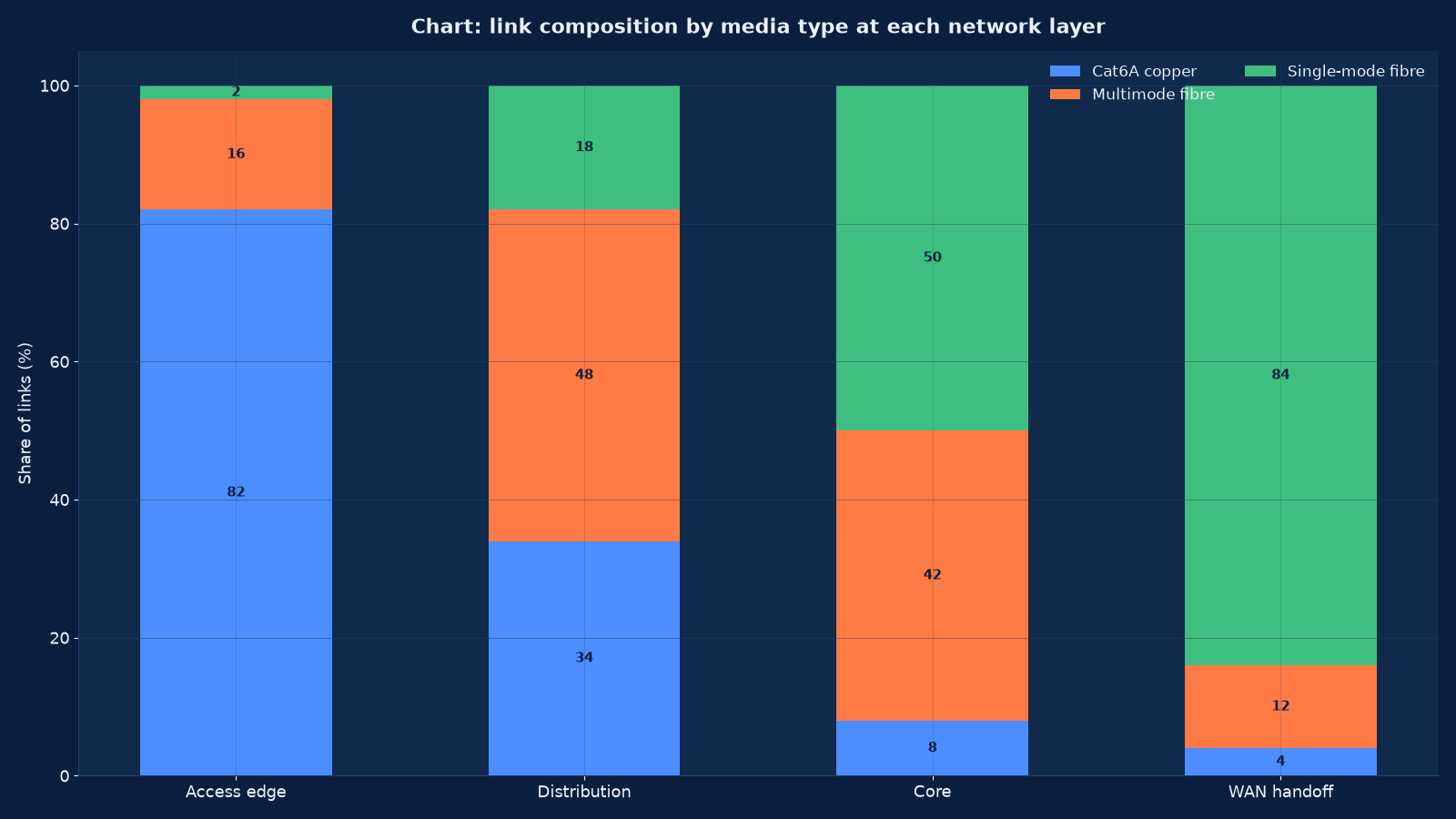
Chart values are an illustrative planning model based on typical UMC engagements and published industry benchmarks. They are not a guarantee of results on any specific project.
LAN Design: The Switching Hierarchy Above the Cable
The local area network layer is where the physical plant becomes a working network, and the design decisions are about capacity, redundancy and the Layer 2 topology. A plant with perfect cabling and a badly designed switching hierarchy still fails, and it fails in ways that look like cable faults.
| Layer | Role | Key design decisions | What goes wrong when it is unplanned |
|---|---|---|---|
| Access | Connects endpoints and access points to the network | Port count with growth, uplink speed, power budget, stacking topology, port security | Oversubscribed uplinks, insufficient power for modern access points, and no redundancy |
| Distribution or aggregation | Terminates access uplinks, applies policy and routing boundaries | Uplink aggregation, first-hop redundancy, the boundary between Layer 2 and Layer 3 | A Layer 2 domain that has grown to include the whole building, with broadcast and loop risk |
| Core | High-speed transport between distribution blocks, the data hall and the WAN edge | Full redundancy, non-blocking capacity, media and transceiver compatibility | A single point of failure at the centre of the network |
| Data hall and server edge | Connects compute and storage to the core | High port density, low latency paths, structured top-of-rack design | Ad-hoc in-rack cabling that cannot be traced or changed without risk |
| WAN edge and handoff | Where the building meets the carrier | Demarcation point, handoff medium, redundancy across carriers and diverse entry paths | A single carrier entering by a single route, which is a total outage waiting for a digger |
Loop prevention and the Layer 2 boundary
The most common structural defect in an undocumented plant is a Layer 2 domain that has grown without anyone deciding it should. Access switches daisy-chained to access switches, VLANs extended across buildings, and a spanning-tree topology that nobody has documented produce a network where one misconnected cable can affect the entire estate. We design the Layer 2 boundary deliberately, document the spanning-tree root and priorities, and make the VLAN map a maintained document rather than a configuration that has accreted.
Power over Ethernet: The Arithmetic That Decides Whether the Radios Work
Power over Ethernet has moved from a convenience to a structural requirement, because the devices being powered are no longer telephones. Modern access points, cameras, building sensors and displays draw power that earlier switches were never designed to supply, and the arithmetic is unforgiving.
| Constraint | How we calculate it | The failure it prevents |
|---|---|---|
| Per-port power class | The class each device actually needs, verified against the manufacturer’s stated maximum rather than its typical draw | An access point negotiating down to fewer radios because the port cannot supply its class |
| Per-switch power budget | The sum of powered ports against the switch’s total budget, with headroom | Ports refusing to power on when the budget is exhausted, which looks like a device fault |
| Peak versus typical draw | Devices draw most during boot, radio transmit and heater operation, not at idle | A plant that works all day and fails during a mass restart |
| Cable resistance over distance | Longer runs and lower-grade cable drop more voltage | A device at the end of a long run that will not power reliably |
| Growth headroom | The devices expected in the next five years, not the ones installed today | A switch replacement programme driven by power rather than by bandwidth |
| Cooling consequence | Powered ports add heat to the room’s load | A room whose cooling was sized for switches and not for the power they now deliver |
| Redundancy behaviour | What happens to powered devices when a switch or uplink fails | Access points and cameras going dark precisely when they are most needed |
We publish the power budget per switch and per room as part of the design, including the growth headroom and the date at which the headroom is expected to be exhausted. It is a small document that prevents a large surprise, and it is the reason our wireless designs are produced together with the cabling design rather than after it.
Certification and Testing: Proving the Plant
Certification is the difference between a cable that has been installed and a link that has been proven. A link-light check tells you the interface negotiated; a permanent-link certification tells you the link meets the category’s performance parameters, and produces a record that can be produced years later when a fault is being argued about.
| Test type | What it proves | Applied to | Deliverable |
|---|---|---|---|
| Permanent-link certification for copper | That the installed link meets the category’s parameters — wire map, length, insertion loss, return loss, and the crosstalk measurements that matter at speed | Every horizontal copper link | A per-outlet record in a queryable format, referencing the label |
| Tier-one fibre testing | Continuity, polarity, length and insertion loss | Every fibre link | Per-link loss records against the calculated loss budget |
| Tier-two fibre testing | Optical time-domain reflectometry to locate and characterise each event in the link | Links that fail tier one, and long or critical backbones | A trace showing where each splice and connector sits, and what it costs in loss |
| Channel versus permanent link | The distinction between testing the installed link and testing it with the patch cords included | Permanent link for certification of the plant; channel where the patch cord is part of the delivered service | Records that state which method was used, because the results differ |
| Post-remediation re-test | That corrected links now pass, and that untouched links were not disturbed | Every outlet affected by remediation work | Before-and-after records per outlet |
We deliver test records in a format that can be searched and reported on, not as a stack of tester printouts. The practical difference appears during the first fault: an engineer with a searchable record establishes in a minute whether the cable is suspect, while an engineer with a paper archive spends the afternoon looking for it and then assumes the problem is software.
Remediation Without an Outage: The Phased Sequence
Remediating a live plant is harder than installing a new one, because the work has to be done without taking the business off the network. The sequence below is what makes that possible, and the discipline is that no floor is started before the previous one is verified and documented.
| Phase | Activity | Risk control |
|---|---|---|
| Phase 0 — baseline | Complete survey, condition scoring, test-record gap analysis and a floor-by-floor work package plan | Nothing is touched until the plant is known; the baseline is the measurement every improvement is reported against |
| Phase 1 — documentation first | Labelling scheme agreed and applied, VLAN and topology captured, as-builts started | Documentation precedes physical work, so a fault during remediation can be diagnosed rather than guessed |
| Phase 2 — rooms and pathways | Room power, cooling, earthing, containment and pathway remediation | Done before horizontal work, so new cable is pulled into a corrected environment |
| Phase 3 — backbone | Riser and backbone replacement or augmentation, with diverse routes where possible | Planned windows, temporary paths, and rollback available at every step |
| Phase 4 — horizontal, floor by floor | Access-layer replacement and re-termination, one floor or zone at a time | Out-of-hours work, per-floor cutover, and the previous floor verified before the next begins |
| Phase 5 — access layer and power | Switch replacement with the power budget deliberate, uplinks made redundant | Power budget confirmed before devices are connected, so nothing negotiates down |
| Phase 6 — certification | Permanent-link and fibre testing across the remediated plant | Records delivered per outlet, with failures re-terminated and re-tested until they pass |
| Phase 7 — handover | As-builts, asset register, labelling record, test records, spare capacity map and the maintenance procedure | The plant handed over as a documented asset, with the condition score re-measured against the baseline |
The condition score is measured again at handover and reported next to the baseline. It is the clearest single statement of what a remediation programme achieved, and it is also what makes the next one cheaper, because the plant entering it is known.
How This Differs From Our Neighbouring Pages
Cabling is the foundation for every other network discipline, and the WAN handoff is where the building’s plant meets the carrier’s. Both relationships have to be documented, because both are where responsibility is argued about during an outage.
| Your question | Right starting point | What it produces |
|---|---|---|
| What can our plant actually support? | This page | A scored condition assessment, a capability statement and a remediation plan |
| Who designs the routing, switching and firewall estate on top of it? | Routing, Switching, Firewall and Network Engineering | The Layer 3 design, routing architecture and firewall engineering that the plant carries |
| The compute and storage estate is the constraint | Computing, Server, Storage and Data Centre Engineering | An estate roadmap, including the data hall whose cabling and power this page designs |
| Access points keep underperforming | Our enterprise wireless offering, built in this same programme | A wireless design whose power budget, uplink capacity and cable category have been verified against the plant |
| Sites cannot reach cloud efficiently | Our SD-WAN and SASE offering, built in this same programme | An overlay design that assumes a WAN handoff with the capacity and redundancy it needs |
| We do not know who is on the network | Our network security and access control offering, built in this same programme | A segmentation and admission design that requires a documented VLAN and topology map to implement |
| Telephony is moving onto the data network | Our unified communications and VoIP offering, built in this same programme | A voice design whose quality depends on the cabling category, the power budget and quality of service end to end |
| Nobody notices faults until users report them | Our network operations and monitoring offering, built in this same programme | A monitoring design that needs the asset register and topology this page produces |
| The facility itself needs work | Our data centre design and build offering, built in this same programme | A facility design whose rooms, power and cooling are engineered rather than inherited |
| An auditor wants evidence about the plant | IT Audit, Compliance & ISO 27001 / SOC 2 Readiness | The test records, as-builts and asset register assembled as audit evidence |
Evidence From Our Work
Physical plant work is rarely published in detail, but the estates below show the environments our cabling and network designs have to serve: multi-site healthcare with server-room build-outs, multi-property hospitality where each site has its own plant, and continuous-operation media where a cable fault is a broadcast fault.
- Global Hospitals — Case Study — switching and routing architecture with a server room build across multiple locations, delivered over a six-to-nine month implementation with twenty-four months of support. A server room build is a cabling, pathway, power and cooling project before it is an equipment project.
- Marriott Hotel Hyderabad — Case Study — managed services, monitoring and maintenance across multi-property operations, where each property holds its own plant and the centre has to know what each one is.
- IT Infrastructure Management for an IT Company — Case Study — twenty-four-by-seven monitoring, preventive maintenance and security management for a media and broadcasting company on a twenty-four month renewable contract, where the physical plant carries signals that cannot be interrupted.
- Apollo Hospitals — Case Study — a multi-campus feasibility study, which is only meaningful against a surveyed plant: coverage predictions are worthless if nobody knows what the access switches can power.
- Fern Hotel Hyderabad — Case Study — hospitality infrastructure across properties, where guest-facing plant and back-of-house plant have different labelling, access and redundancy requirements.
- Enterprise Computer Networks: Trends, Operations, and Careers — the operations discipline a documented plant enables, and why the documentation is what makes the difference.
- Best IT Company in Lucknow: What Growing Businesses Need from a Technology Partner — how to assess an infrastructure supplier, including the questions to ask about testing and documentation before awarding the work.
- our Technology archive — further writing on network operations, infrastructure standards and the discipline behind them.
Frequently Asked Questions About Structured Cabling, LAN and WAN Engineering
What category of cable should we install?
For new access-layer work the default is Cat6A, because it carries 10 GbE to a hundred metres with the alien crosstalk performance to prove it, and the plant will outlive four generations of equipment. Cat6 remains common in existing plants and can serve 1 GbE well, but it is a poor choice where multi-gigabit access points are expected. The decision should be driven by what the access layer will carry in five years, not by today’s switch speeds.
Single-mode or multimode fibre?
By distance and by transceiver economics rather than by habit. Multimode suits building-scale backbones and in-rack links where its transceivers are convenient. Single-mode is now the better lifetime choice for anything between buildings, for long risers and for WAN handoff, because its reach is effectively unlimited and its optics have become inexpensive. Figure 3 shows the pattern a deliberate design produces.
Why does labelling matter so much?
Because it converts fault diagnosis from elimination into lookup. On a plant where outlets, panels, cores and rooms follow one documented scheme, an engineer can identify a link in a minute. On an unlabelled plant the same fault takes hours, requires a second person, and carries the risk of unplugging something important to test something else. It is also the cheapest control in this entire discipline.
What is a permanent-link test and why is it different from a channel test?
A permanent-link test certifies the installed cabling — the horizontal run and its terminations — excluding the patch cords at each end. A channel test includes those patch cords. The permanent link is what you are certifying as a fifteen-year asset, so it is what we test for the plant record; a channel test is appropriate where the patch cord is part of a delivered service. The records state which method was used, because the results differ.
How often should an existing plant be re-certified?
Not on a fixed cycle, but on events: after any remediation, after a switch or access-point generation upgrade that raises the speed on existing links, and when a fault cannot be explained from the equipment side. What should be continuous is the record — every outlet should have a test result on file, with its date, so a gap is visible rather than assumed to be fine.
What is the biggest cause of Wi-Fi problems in an existing building?
Usually the plant under it, not the radios. Access points that need more power than the switch port supplies negotiate down to fewer radios; uplinks that cannot carry the aggregated wireless traffic produce congestion that looks like interference; and cable category that cannot support multi-gigabit access points caps throughput before the radio does. We assess the cabling and power budget before recommending any wireless hardware.
How much spare capacity should we build in?
Enough that the next project does not have to open the ceiling. In practice that means pathway fill well below the maximum with the growth route documented, patch panel ports in reserve, spare backbone strands, and switch ports and power budget for the devices expected in five years. Spare capacity is cheap at installation and very expensive afterwards, so we record it per route as a delivered asset.
Can a live plant be remediated without an outage?
Yes, if it is sequenced properly — which is why the phasing in this page exists. Documentation and labelling come first so faults can be diagnosed during the work; rooms and pathways are corrected before horizontal cable; and horizontal work proceeds floor by floor, out of hours, with the previous floor verified before the next begins. What causes outages is starting physical work on a plant nobody has documented.
Where does the carrier’s responsibility end?
At the demarcation point, which should be a documented physical location with a documented handoff medium. Everything on the building side — the path from the demarcation to your WAN edge, the containment it runs in, and the redundancy of that route — is yours. We document the demarcation explicitly, because during an outage the argument is always about which side of it the fault lies.
What should we ask a cabling contractor before awarding the work?
Four things: what labelling scheme they will apply and whether they will deliver it as data rather than photographs; whether every outlet will be permanent-link certified with records in a searchable format; whether they will deliver as-built drawings that match the installed plant; and whether the quotation includes pathway growth capacity and room power and cooling assessment. A contractor who hesitates on the second and third questions is quoting a different service from the one you need.
How does the plant relate to the asset register?
The register is what makes the plant queryable: which outlet is where, what it connects to, which switch port, which VLAN, when it was tested and what the result was. Without it the as-builts are a document nobody opens. We deliver the register as structured data with the labelling scheme as its key, so it can be maintained by whoever operates the network afterwards.
What evidence do we get at the end of an engagement?
The scored condition assessment with the baseline percentages, the design documents covering media, pathways, rooms, switching hierarchy and power budget, the labelling scheme and its application record, permanent-link and fibre test records for every link delivered, as-built drawings, the asset register, the spare capacity map, and the re-measured condition score at handover.
Find Out What Your Plant Can Actually Support
Most organisations cannot answer that question, and the ones that can usually wish they had asked it earlier. We will survey the plant, score its condition, and give you a written capability statement: what it can carry today, what it will carry in five years, what has no test record, and what the remediation would cost floor by floor. The survey changes the conversation, because a plant at 35 per cent labelled and 15 per cent tested is a quantified risk rather than a vague concern.
Contact Unified Management Consulting to arrange a confidential first conversation.
Related Services
The physical plant carries everything above it. These are the engagements it most often runs alongside:
- Routing, Switching, Firewall and Network Engineering — the Layer 3 and security design that runs on the plant, and the topology this page documents.
- Computing, Server, Storage and Data Centre Engineering — the data hall and compute estate whose structured cabling, power and containment are designed here.
- Managed IT Infrastructure & IT AMC Services — operating the plant afterwards, where the asset register and test records decide how fast faults are found.
- IT Audit, Compliance & ISO 27001 / SOC 2 Readiness — the documentation, records and access controls an auditor will ask to see.
- IT Help Desk & Remote Support Services — the first line that diagnoses physical-layer faults, which is only fast when the plant is labelled and documented.
- Cybersecurity Services — the wider security programme that physical access control, room security and documentation support.
- Enterprise Systems Integration & Tech-Stack Consolidation — consolidation programmes that change port counts, uplink capacity and room loads, and should be sized against the plant rather than around it.
- Enterprise Wireless & Wi-Fi 6 Design Services — predictive surveys, Wi-Fi 6 and 6E design, roaming and the coverage evidence taken on site
- Network Security, Segmentation & NAC Services — segmentation, NAC, firewall policy and the change control that keeps the boundary auditable
- NOC & Network Monitoring Services — 24×7 monitoring, alert thresholds, incident response and the reporting that turns uptime into a number
- SD-WAN & SASE Design and Rollout Services — SD-WAN and SASE rollout with application policy, transport independence and measurable failover behaviour
- Unified Communications & VoIP Services — unified communications and VoIP design, number planning, QoS, contact centre integration and call quality