
Chart values are an illustrative planning model based on typical UMC engagements and published industry benchmarks. They are not a guarantee of results on any specific project.
Wireless is the only part of an enterprise network whose medium is shared with everyone else in the building, including the neighbours, the microwave oven in the staff room and every device a visitor walked in with. It is therefore the only part that cannot be designed from a specification sheet. It has to be designed from a survey, built against a power budget somebody calculated, and validated by measuring the result — because the alternative is a network that works in the demonstration and fails in the warehouse.
Enterprise wireless engineering at Unified Management Consulting is the design, deployment and validation of Wi-Fi as an infrastructure service rather than as an amenity. It covers the requirement definition that decides what coverage, capacity and application support each zone actually needs; the predictive and validated survey work; the radio-frequency design including channel plan, power levels and access point placement; the wired side that supplies power and bandwidth to every radio; the controller or cloud management architecture; the security model separating corporate, guest, operational and Internet-of-Things traffic; and the post-installation validation that proves the design was achieved.
We deliver wireless programmes for environments where the network carries something that matters: clinical estates where voice badges and imaging devices roam between wings, warehouses where handheld scanners stop working the moment a device roams badly, manufacturing plants with metal that reflects radio frequency in ways a predictive model will not guess, hospitality properties where guest experience is a commercial product, campuses with high-density lecture theatres, and offices whose device count per person has tripled since the last deployment was sized.
📶 Enterprise Wireless (Wi-Fi 6 / 6E) — Quick Summary
| Component | What We Deliver |
|---|---|
| Requirements definition | Coverage, capacity and application requirements captured per zone from the people who work in them — the step that decides whether the design is for coverage or for capacity, which are different designs. |
| Site survey — predictive and validated | Predictive modelling against floor plans and materials, then a post-installation survey that measures what was actually delivered. |
| Radio frequency design | Access point placement, channel plan, transmit power and the cell-size decisions that determine whether roaming works. |
| Wi-Fi 6 and 6E capability planning | What the new standards actually buy in your environment, and whether the estate is client-limited rather than radio-limited. |
| Wired infrastructure and power budget | Cable category, uplink speed and power over Ethernet capacity per switch, verified against the access points’ stated maximum draw. |
| Management architecture | Controller-based, cloud-managed or distributed, chosen against estate size, resilience requirements and how the network will be operated. |
| Security and network separation | Corporate, guest, operational and device traffic on separate networks with their own admission and inspection paths. |
| High-density design | Lecture theatres, stadiums, conference floors and any zone where device count rather than area sets the access point count. |
| Roaming and voice readiness | Roaming behaviour tested with real client types, and the prioritisation and handoff characteristics wireless voice depends on. |
| Industrial, warehouse and outdoor coverage | Design for environments with reflection, interference, height, dust and temperature constraints. |
| Validation and optimisation | Measured throughput, coverage, roaming and interference reporting, with power and channel tuning done against measurements rather than defaults. |
| Lifecycle and operations handover | Firmware baselines, the monitoring that detects degradation, and the runbooks for the team that will operate it. |
Coverage or Capacity: The Requirement That Decides Everything Else
A wireless design is driven by one of two requirements, and which one dominates changes the answer completely. Coverage-driven design places access points so that every area has adequate signal — which produces a modest device count and works well for offices where people carry one or two devices. Capacity-driven design places access points so that each radio serves few enough clients to give them all a usable share of airtime — which produces a much higher device count and is the right answer anywhere the device density is high.
| Requirement | Coverage-driven | Capacity-driven | How to tell which you need |
|---|---|---|---|
| What sets the access point count | Floor area and the signal level required at the cell edge | Concurrent clients per radio and the airtime each application consumes | Count the devices in the busiest zone at the busiest hour, not the floor area |
| Typical cell size | Large — access points placed for reach | Small — power reduced deliberately so cells do not overlap usefully | Large cells on a capacity estate are the commonest cause of a slow network with full signal bars |
| Transmit power | Higher, to reach | Lower, to shrink cells and force clients onto the nearest access point | If the design has no stated power plan, it is coverage-driven by default |
| Channel plan | Standard non-overlapping set | Careful reuse with band steering and, where available, the additional channels of 6 GHz | Channel reuse distance has to be planned, not automated blindly |
| Client behaviour assumption | Clients associate to the strongest signal | Clients make poor roaming decisions unless the network constrains them | Sticky clients — the reason capacity designs reduce power and use client steering |
| Where it applies | Corridors, warehouses with few users, outdoor areas, low-density offices | Open-plan offices, lecture theatres, clinical wings, conference floors, dense retail | Most modern estates need both, zone by zone |
The requirement definition is the deliverable that makes this decision explicit. We capture it per zone with the people who work there, and we publish the device count, the application mix and the coverage target each zone is designed to — because a design that does not state its requirement cannot be validated against it, and an estate that cannot be validated will be argued about forever.
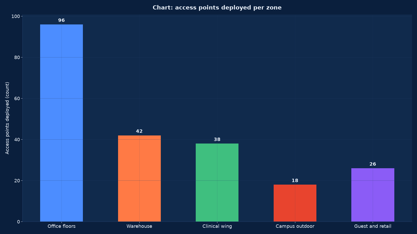
Chart values are an illustrative planning model based on typical UMC engagements and published industry benchmarks. They are not a guarantee of results on any specific project.
Zone by Zone: Why One Estate Needs Several Designs
Different zones fail differently, and a design that treats an estate as one uniform requirement produces a network that works in the boardroom and fails in the plant room. The zone inventory below is the shape of a real multi-use estate, and the design parameters differ per row.
| Zone | Dominant requirement | The specific difficulty | Design response |
|---|---|---|---|
| Open-plan office floors | Capacity — many devices per person, video calls, cloud applications | Sticky clients and co-channel contention across a large open space | Small cells, reduced power, band steering, and access point density set by client count |
| Meeting rooms and huddle spaces | Capacity in bursts, with high-quality video | A room full of devices joining simultaneously, with walls that attenuate unevenly | An access point per room rather than relying on corridor coverage |
| Clinical wings | Roaming continuity for voice badges and clinical devices | Devices that must not drop a session while moving between wings, and equipment that interferes | Cell overlap planned for handoff, roaming validated with the actual device models, and interference surveyed on site |
| Warehouse and logistics | Coverage for handheld scanners across a large volume | Racking that reflects and blocks signal, and scanners with weak radios and poor roaming logic | Access points positioned for the racking layout as built, not as planned, with the scanner models tested |
| Manufacturing and plant | Coverage plus resilience in a hostile environment | Metal reflection, motor interference, dust, temperature and vibration | Industrial-rated access points, protective mounting, a measured interference survey and spares held on site |
| Lecture theatres and event spaces | Extreme density for a fixed period | Several hundred clients in one cell, all contending for the same airtime | High-density design with directional antennas, very small cells and admission expectations set with the business |
| Guest and retail areas | Isolation and capacity from unknown devices | Uncontrolled device types, high churn, and a security boundary that must not leak | A physically or logically separate network with its own egress and no path to corporate traffic |
| Outdoor and campus | Coverage across distance with variable client capability | Weather, mounting, power delivery over distance and regulatory power limits | Directional antennas, weather-rated enclosures, and a power budget that accounts for long cable runs |
| Plant rooms, risers and basements | Coverage for devices and staff who rarely go there | Often omitted from the design and then found to be where the fault is | Included explicitly in the zone inventory, with a stated minimum requirement |
Zone-by-zone design is more work than an estate-wide rule and it is the only approach that produces a network that works everywhere it is needed. The warehouse row is the one that most often surprises clients: the access point positions that a predictive model produces against an empty building are frequently wrong once the racking is installed, which is why the validated survey after fit-out is not optional in that environment.
Radio Frequency Design: Power, Channels, Bands and the Interference Nobody Modelled
Radio frequency design is the part of a wireless programme that cannot be automated away, because every parameter trades against another and the trade depends on the zone. The four decisions below are the ones that determine whether a deployed network behaves.
| Parameter | The trade | What a good design states | The symptom of getting it wrong |
|---|---|---|---|
| Transmit power | Higher power extends reach but grows the cell, which increases co-channel contention and makes clients stick to a distant access point | A power plan per zone, usually asymmetric between the 2.4 and 5 GHz bands | Full signal bars and slow throughput, which is almost always oversized cells |
| Channel plan and reuse | Fewer channels available means more reuse, and reuse distance has to exceed the range at which clients can hear each other | A documented channel map with reuse distance, revised after the validated survey | Co-channel interference that appears as retries and low modulation rates |
| Band selection and steering | 2.4 GHz reaches further and is more congested; 5 GHz is faster and shorter-ranged; 6 GHz adds clean spectrum where clients support it | Steering policy per zone with an explicit statement of which clients cannot be steered | Legacy devices stranded on a congested band while clean spectrum goes unused |
| Cell edge target | The minimum signal level the design guarantees, which sets access point spacing | A stated level per zone — commonly around −67 dBm for data and higher for voice | A design that cannot be validated, because nobody knows what it promised |
| Antenna type and orientation | Omnidirectional for general coverage, directional for distance and density, with orientation mattering as much as type | Specified per zone with mounting detail | Signal delivered into a corridor or a ceiling void instead of into the space that needs it |
| Minimum data rates | Disabling the lowest rates shrinks cells and reduces management overhead, but excludes legacy clients | A stated minimum per band, with the excluded devices enumerated | Either oversized cells or devices that cannot associate, depending on which way the error fell |
Interference is surveyed, not assumed
Every wireless design has to account for what else occupies the spectrum in that building, and the only way to know is to measure it on site. Non-Wi-Fi interferers — microwave ovens, cordless equipment, some industrial machinery, poorly shielded medical and plant equipment — produce degradation that no predictive model anticipates and that presents to users as random slowness. Our surveys record the interference environment per zone, and the design is adjusted against it rather than deployed on top of it.
Wi-Fi 6 and 6E: What Is Real, and What Depends on the Clients
Wi-Fi 6 brought genuine improvements that matter in enterprise environments, and Wi-Fi 6E added clean spectrum. Neither is a reason to replace an estate that is performing, and both are commonly oversold by people who have not counted the clients.
| Capability | What it does | Where it genuinely helps | Where it does not |
|---|---|---|---|
| Orthogonal frequency-division multiple access | Lets one transmission serve several clients simultaneously instead of one at a time | High-density zones with many small transfers — offices, retail, lecture theatres | A warehouse with ten scanners, where airtime was never the constraint |
| Basic service set colouring | Lets an access point ignore a neighbouring cell’s traffic instead of deferring to it | Dense deployments where cells inevitably overlap | Sparse deployments with large cells and little overlap |
| Target wake time | Lets a client sleep until its scheduled transmission | Battery-powered sensors and Internet-of-Things devices | Laptops and phones, which manage their own power |
| 1024-QAM modulation | More data per symbol where the signal is clean | Close-range, high-throughput sessions in a good radio environment | Anywhere with interference, where the modulation rate falls back regardless |
| 6 GHz spectrum in Wi-Fi 6E | A large block of clean channels with no legacy devices in it | Dense estates where 5 GHz reuse is exhausted — provided the clients support it | An estate whose clients are five years old, which is most of them until a refresh cycle completes |
| Multi-link operation in later standards | Uses more than one band simultaneously for a session | Latency-sensitive and high-throughput applications on supported clients | The great majority of currently deployed enterprise clients |
The honest question is whether your estate is radio-limited or client-limited. If the devices in use do not support the newer standards, replacing the access points improves almost nothing except the specification sheet, and the money is better spent on density, power tuning and the wired side. We say so when it is true, and we base it on a client capability survey rather than on an assumption.
Chart values are an illustrative planning model based on typical UMC engagements and published industry benchmarks. They are not a guarantee of results on any specific project.
The Wired Side: Power, Cable and Uplink Arithmetic
The wired side decides whether the radios can work, and it is the part of a wireless programme most often specified by someone who has not calculated it. Three constraints matter: what the cable can carry, how much power the switch can deliver, and how much bandwidth the uplink has.
| Constraint | What has to be true | The failure when it is not |
|---|---|---|
| Cable category | Sufficient to carry the access point’s uplink speed to its distance — multi-gigabit radios on cable that only supports 1 GbE are throttled before the radio is | An access point capable of several gigabits delivering one, and a survey that cannot explain why |
| Power over Ethernet class and budget | The switch port must supply the access point’s stated maximum draw, and the switch’s total budget must cover all its powered ports with headroom | Radios disabled or reduced at boot, access points negotiating to a lower power class, and ports that refuse to power on when the budget is exhausted |
| Peak versus typical draw | Access points draw most during transmit peaks, radio start-up and any heating element, not at idle | A network that works all day and misbehaves after a mass restart or a firmware upgrade |
| Uplink capacity | The aggregate wireless throughput of an access point’s clients must fit its uplink, and the access switch’s uplink must carry all its access points | Congestion that presents as wireless interference and is not |
| Cable distance and resistance | Long runs and lower-grade cable drop more voltage, which matters most outdoors and in warehouses | Access points at the end of long runs that will not power reliably |
| Switch redundancy and stacking | What happens to every access point on a switch when that switch fails | A single switch fault taking a whole floor’s wireless dark, with no local diagnosis possible |
| Management and monitoring reachability | The management network must reach every access point and its controller or cloud service | An estate that cannot be configured, upgraded or diagnosed remotely |
This is why our wireless designs are produced together with the cabling and switching design rather than after it. A wireless programme handed a plant it cannot use produces either an access point selection constrained by the switch estate or a switch replacement programme nobody budgeted for, and both are discovered late.
Management Architecture and the Firmware Baseline
Management architecture is a decision about resilience, scale and who operates the estate. All three models work; they differ in where the failure is and who has to be awake when it happens.
| Model | How it works | Resilience behaviour | Suits |
|---|---|---|---|
| Controller-based, on-premises | Access points tunnel to one or more controllers that hold configuration, policy and client state | Controller failure affects new associations and roaming; a resilient pair removes the single point | Estates that want local control, have a data centre to host it, and operate their own network team |
| Cloud-managed | Access points are configured and monitored from a cloud service, with data-plane decisions local to the device | Cloud unreachability usually does not stop forwarding, but it stops changes and visibility | Distributed estates with thin local teams and many small sites |
| Distributed or controllerless | Access points coordinate among themselves without a central appliance | No central failure domain, and less central visibility | Smaller estates, or zones where a controller dependency is unacceptable |
| Hybrid | One model per zone or per site class, managed as a single policy set | Depends on the components, and has to be documented | The commonest real answer for multi-use estates with plant, clinical and office environments |
Firmware is a lifecycle programme, not an update
Wireless estates carry dozens or hundreds of devices running the same software, so a firmware problem is an estate-wide problem. The discipline is a validated baseline per estate, a staging group that is upgraded first, a documented rollback, and an upgrade window that accounts for the fact that access points reboot — which means the wired power budget and the client re-association behaviour both matter at that moment. An estate upgraded in one action across every site is an estate that fails in one action across every site.
Security: Admission, Separation and What Each Network May Reach
Wireless is a shared, unbounded medium, so the security model has to assume that anyone within range can attempt to join. The controls are admission, separation and inspection, and they are applied differently per network because the networks carry different things.
| Network | Admission control | Separation requirement | Inspection and egress |
|---|---|---|---|
| Corporate | Certificate- or identity-based authentication tied to the directory, with device posture checked where possible | Isolated from guest and device traffic, with restricted paths to sensitive systems | Inspected egress, and access to internal resources governed by identity rather than by network position |
| Guest | Captive portal or voucher-based access with no authentication dependency on the corporate directory | Complete isolation from corporate traffic — the single most important boundary in a wireless design | Egress only, filtered, rate-limited, and logged with the session tied to an identity where one was captured |
| Operational technology and plant devices | Device-profiling-based admission, since most such devices cannot perform modern authentication | Segmented by function and by safety consequence, with lateral paths closed by default | Inspection rarely possible on the devices themselves, so control is by segmentation and monitoring instead |
| Internet of Things and sensors | Profile-based admission with a registered device inventory | Separated per device class, since compromise of one class should not reach another | Egress tightly restricted; most of these devices should not be able to reach the internet at all |
| Voice and clinical devices | Authenticated where the device supports it, profiled where it does not | Prioritised traffic on its own path, with quality of service honoured end to end | Session-level visibility, because a dropped voice session is reported as a network fault and diagnosed as one |
| Bring-your-own-device | Identity-based access with posture requirements, and a clear statement of what such devices may reach | Treated as guest-class for internal access even when authenticated | Inspected egress and restricted internal paths, since the device is not managed |
Rogue access point detection belongs in the same model: an estate that cannot tell you which access points are authorised cannot tell you which are not. Detection is a monitoring capability with a defined response, and the response has to be a process rather than an alert nobody owns.
Roaming: A Joint Property of the Network and the Client
Roaming is the behaviour users notice most and the one designed least. It is a joint property of the network and the client: the network offers cells, and the client decides when to move between them — and clients decide badly, holding onto a distant access point until the session degrades rather than failing over cleanly.
| Factor | What the network controls | What the client controls | Design response |
|---|---|---|---|
| When to roam | Cell size and overlap, by power and placement | The signal threshold at which it decides to look for another access point | Reduce power to shrink cells so the client has a better option available sooner |
| How fast to roam | Support for the fast-roaming standards the client understands | Which standards the client actually implements | Enable the standards broadly, and test with the specific device models in the estate |
| Whether the session survives | Authentication caching and controller or cloud state | Whether the application tolerates the handoff delay | Design for the least tolerant application in the zone, not the average one |
| Which band to use | Steering policy and band availability | Whether the client accepts the steering | Steer where clients permit it, and accept that some devices cannot be steered at all |
| Voice handoff specifically | Prioritisation, cell overlap and fast-roaming support | The device’s own roaming logic, which varies widely between models | Test the actual voice device in the actual environment before committing to a design |
| Scanner behaviour in a warehouse | Cell layout against the racking as built | Legacy roaming logic that is often poor and rarely configurable | Design around the device rather than expecting the device to adapt, and hold spares of a model known to work |
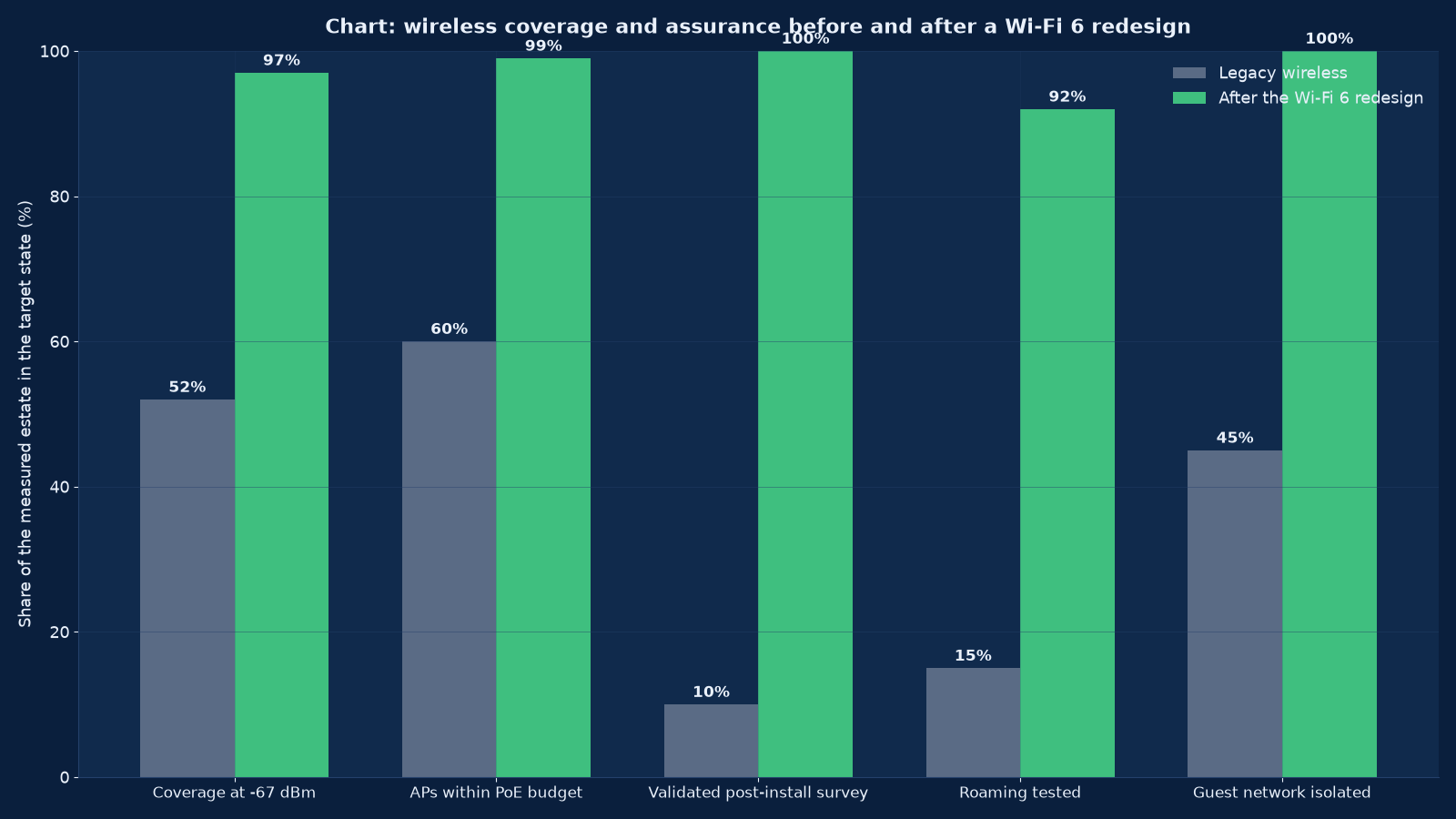
Roaming is validated by walking the environment with the actual devices and recording what happens, not by reading the coverage map. The test we run is per device class per zone: how many handoffs occur on a defined route, how long each takes, and whether the session survives. A roaming test pass rate of 92 per cent across the estate, which is what Figure 1 reports, means the remaining 8 per cent are documented rather than hoped away.
Validation: Predictive, Measured and Then Tested With Real Devices
Validation is what turns a deployment into a delivered service. It has three parts, and an estate that has only the first has a predictive model with equipment installed against it.
| Validation stage | What it produces | Why it is not skippable |
|---|---|---|
| Predictive survey before installation | A model of access point positions, channel plan and expected coverage against the floor plans and materials | Without it the deployment is a guess about quantity and placement, and the cost of correcting it afterwards is high |
| Post-installation validated survey | Measured coverage, signal, noise, throughput and interference in the built environment | The built environment differs from the model — furniture, racking, fit-out and people all attenuate — and only measurement reveals by how much |
| Application and device testing | The actual applications on the actual device models, in the zones where they are used | Coverage and throughput do not predict whether a scanner roams cleanly or a voice badge holds a session |
| Roaming and handoff testing | Handoff counts, durations and session survival on defined routes per device class | The behaviour users complain about, which no coverage map shows |
| Load testing at density | Behaviour with a realistic number of concurrent clients, not one tester | Airtime contention appears only under load, and a design validated at low density proves nothing about a lecture theatre |
| Tuning against measurements | Power and channel adjustments made from the survey data, with the before-and-after recorded | Default radio settings are optimised for no environment in particular |
| Handover documentation | As-built coverage maps, the design parameters, the client inventory, firmware baseline, monitoring thresholds and runbooks | Without it the estate cannot be operated or extended by anyone other than the installer |
We report validation as a scored result against the stated requirement — coverage at the design target, throughput per zone, roaming test pass rate, interference level — so that “the wireless is finished” means something measurable. That score is also the baseline against which future degradation is detected, which is the part most estates never have.
Operating the Estate: What Degradation Looks Like Before Anyone Complains
A wireless estate degrades gradually and invisibly, because the symptoms present as user complaints rather than as faults. The monitoring that catches it is specific, and most of it is not available from a coverage map.
| What we monitor | What it detects early | Threshold principle |
|---|---|---|
| Client count per access point and per radio | Density creep — the estate growing without the design being revisited | Set against the design’s clients-per-radio figure, not against the hardware maximum |
| Retries, modulation rates and airtime utilisation | Interference and co-channel contention before users notice | Trended per zone, since a change in one zone’s behaviour usually has a physical cause |
| Channel utilisation per band | A band becoming saturated, which is the signal to redesign density | Alerting at a utilisation level where experience is still acceptable |
| Rogue and adjacent access points | Unauthorised devices and growing external interference | Any rogue device on the corporate network alerts immediately |
| Client failure and association rejection rates | An authentication or posture problem, or a firmware regression | Any sustained rise is investigated as a change, not as noise |
| Roaming event rates and durations | A roaming regression after a firmware or configuration change | Compared against the validated baseline per device class |
| Access point availability and reboot events | Power problems, firmware crashes and switch faults | Any unexplained reboot alerts, since access points do not reboot themselves |
| Power over Ethernet status per port | A budget problem reducing radio capability | Any port negotiating below its expected power class alerts |
These are the measurements that keep a wireless estate honest between refresh cycles, and they belong in the same operating model as the rest of the network. An estate monitored only for access point availability is an estate whose users are the monitoring system.
How This Differs From Our Neighbouring Pages
Wireless sits directly on top of the physical plant and directly underneath the security and operations disciplines. Neither relationship is optional.
| Your question | Right starting point | What it produces |
|---|---|---|
| Our wireless is slow and we do not know why | This page | A requirement definition, a validated survey, and a design with the density, power and channel decisions stated per zone |
| Who designs the switching and routing the wireless depends on? | Routing, Switching, Firewall and Network Engineering | The Layer 2 and Layer 3 design, including the segmentation and prioritisation wireless traffic needs |
| The plant cannot power the access points we want | Our structured cabling and LAN/WAN engineering offering, built in this same programme | A cable category, uplink capacity and power budget that the wireless design is built against rather than discovered afterwards |
| Guest, device and corporate traffic must not mix | Our network security and access control offering, built in this same programme | Admission control, profiling and segmentation covering wireless clients that cannot authenticate normally |
| The wider security posture is the question | Cybersecurity Services | The security programme the wireless boundary has to fit, including rogue detection and the guest isolation requirement |
| Sites are distributed and connectivity varies | Our SD-WAN and SASE offering, built in this same programme | A WAN design whose path quality the wireless estate inherits at every branch |
| Voice has to work on the wireless | Our unified communications and VoIP offering, built in this same programme | A voice design with the roaming, prioritisation and handoff behaviour tested against the actual devices |
| Nobody notices degradation until users complain | Our network operations and monitoring offering, built in this same programme | A monitoring design using the radio-level telemetry in this page, with thresholds against the validated baseline |
| Devices that cannot authenticate are joining the network | IT Audit, Compliance & ISO 27001 / SOC 2 Readiness | The admission, logging and separation evidence an auditor will ask for |
| Who keeps it running afterwards? | Managed IT Infrastructure & IT AMC Services | A managed service with the firmware baseline, monitoring thresholds and runbooks this page specifies |
Evidence From Our Work
Wireless feasibility is the one infrastructure discipline where a measured study can be published, because its output is a recommendation rather than a configuration. The Apollo engagement is the clearest example in our portfolio of the method this page describes.
- Apollo Hospitals — Case Study — a feasibility assessment for an 802.11n Cisco wireless deployment across multiple hospital campuses, documented at 1,127 words of analysis. A multi-campus clinical estate is the hardest case for wireless design: roaming clinical devices, interference from medical equipment, zones with very different density requirements, and an availability expectation that does not tolerate a coverage gap.
- Global Hospitals — Case Study — switching and routing across multiple locations with a server room build, a six-to-nine month implementation and twenty-four months of support. Wireless designs onto this kind of estate inherit whatever the switching layer can power and carry.
- Marriott Hotel Hyderabad — Case Study — managed services, monitoring and maintenance across multi-property hospitality operations, where guest wireless is a commercial product and its quality is judged by people who have no interest in the explanation.
- Fern Hotel Hyderabad — Case Study — hospitality infrastructure across properties, where guest and back-of-house wireless have to be separated and both have to work in buildings not designed for either.
- IT Infrastructure Management for an IT Company — Case Study — twenty-four-by-seven monitoring, preventive maintenance and support for a media and broadcasting company, where high-density event and studio environments push wireless capacity harder than any office does.
- Enterprise Computer Networks: Trends, Operations, and Careers — the operations discipline a wireless estate depends on, and why radio-level telemetry is what makes degradation visible before users report it.
- Best IT Company in Lucknow: What Growing Businesses Need from a Technology Partner — how to assess an infrastructure supplier, including whether they validate a wireless deployment by measurement or by opinion.
- our Technology archive — further writing on network operations, device strategy and the engineering behind them.
Frequently Asked Questions About Enterprise Wireless and Wi-Fi 6
How many access points do we need?
It is not a function of floor area, which is the commonest way this question is answered badly. Access point count is set by whichever is larger: the coverage requirement for the zone’s geometry and materials, or the capacity requirement from the number of concurrent clients and what they do. A warehouse needs few access points across a large area because there are few users; a lecture theatre needs many in a small one. We define the requirement per zone and then size against it.
Should we upgrade to Wi-Fi 6 or 6E?
Only if your estate is radio-limited rather than client-limited. If most devices in use do not support the newer standards, new access points improve almost nothing measurable, and the money is better spent on density, power tuning, interference resolution and the wired side. We run a client capability survey before recommending a refresh, and we will tell you if the honest answer is to wait for the device refresh cycle.
Why is our wireless slow when the signal is full?
Usually because the cells are too large. Full signal at a distance means the client is holding onto a far access point, sharing its airtime with many other clients, and being steered nowhere. The fix is a power plan that shrinks cells so clients have a nearer option, plus verification that the co-channel contention has actually reduced. The second commonest cause is an uplink or power constraint on the wired side that the radio cannot exceed.
What is a validated survey and why is it different from a predictive one?
A predictive survey models coverage from floor plans, materials and access point positions before installation. A validated survey measures the built environment afterwards. They differ because furniture, racking, fit-out, glass and people attenuate signal in ways a model cannot anticipate — most dramatically in warehouses, where installed racking changes the radio environment completely. A deployment with only a predictive survey has a hypothesis, not a delivered service.
Can our warehouse scanners work reliably?
Yes, but the design has to accommodate them rather than expect them to adapt. Legacy handheld scanners commonly have weak radios, poor roaming logic and little configurability, so cell layout has to be planned against the racking as built, access point positions validated after the racking is installed, and the specific scanner models tested on defined routes. This is the zone where a design produced from an empty building’s floor plan most reliably fails.
How do we keep guest traffic away from corporate traffic?
Complete separation, enforced at the network layer rather than by a firewall rule that could be misconfigured: a separate network with its own egress path and no route to internal resources, admission by captive portal or voucher, filtered and rate-limited internet access, and sessions logged with whatever identity was captured. Guest isolation at 100 per cent, which Figure 1 reports as the post-redesign state, means no zone on the estate has a path from guest to corporate traffic.
What is the power over Ethernet requirement and why does it keep coming up?
Because it silently reduces radio capability. Each access point has a stated maximum draw — highest during transmit peaks, not at idle — and the switch port must supply that class while the switch’s total budget covers all its powered ports with headroom. When the budget is short, access points disable radios or negotiate down, and the estate reports full signal with poor throughput. We publish the power budget per switch and per zone as part of the design.
Does wireless voice need a different design?
Yes. Voice needs a higher cell-edge signal target, planned cell overlap for handoff, prioritisation honoured end to end, fast-roaming standards supported, and validation with the actual voice device models — because roaming behaviour varies widely between devices and the network cannot compensate for a device that will not let go of a distant access point. We test the real device in the real environment before committing the design.
How do we handle devices that cannot authenticate?
With profiling-based admission control rather than by opening the network. Most operational technology, printer, sensor and legacy device populations cannot perform certificate or identity-based authentication, so they are identified by their behaviour and characteristics, placed on a segmented network appropriate to their function, and monitored — with lateral paths closed by default. The inventory of such devices is itself a deliverable, because an estate cannot secure what it has not enumerated.
How often should a wireless estate be re-surveyed?
On events rather than on a fixed cycle: after any significant physical change to the building or the racking, after a client refresh that changes device capability, after a firmware or configuration change that affects radio behaviour, and when a zone’s device count has grown materially. Continuous monitoring of client counts, retries, modulation rates and channel utilisation catches gradual degradation between surveys.
What evidence do we get at the end of a wireless programme?
The per-zone requirement definition with device counts and coverage targets, the predictive survey and its assumptions, the radio frequency design with power and channel plans, the wired design with cable category and power budget per switch, the post-installation validated survey with measured coverage and throughput, application and roaming test results per device class, the tuning record with before-and-after measurements, the security model per network, the firmware baseline and upgrade procedure, and the monitoring thresholds and runbooks for operations.
Find Out Whether Your Wireless Is Radio-Limited or Client-Limited
That single question decides whether the estate needs new access points, a different power plan, a better wired supply or nothing at all — and it can only be answered by measurement. We will define the requirement per zone with the people who work in them, survey the built environment, test the actual devices your staff actually carry, and give you a scored validation against a design that states what it promised.
Contact Unified Management Consulting to arrange a confidential first conversation.
Related Services
Wireless depends on the plant beneath it and the operations around it. These are the engagements it most often runs alongside:
- Routing, Switching, Firewall and Network Engineering — the switching, segmentation and prioritisation design that wireless traffic runs on, and the uplink capacity its radios consume.
- Cybersecurity Services — the security programme a shared, unbounded medium has to fit, including guest isolation and rogue detection.
- Managed IT Infrastructure & IT AMC Services — operating the estate afterwards, with the firmware baseline and monitoring thresholds this page specifies.
- IT Audit, Compliance & ISO 27001 / SOC 2 Readiness — the admission, separation and logging evidence an auditor will ask to see.
- IT Help Desk & Remote Support Services — the first line that triages wireless complaints, which is only fast when radio-level telemetry is available.
- Enterprise Systems Integration & Tech-Stack Consolidation — device and application consolidation that changes client counts per zone, and should be sized against the wireless design rather than after it.
- Computing, Server, Storage and Data Centre Engineering — the controller and management infrastructure a larger wireless estate depends on.
- Network Security, Segmentation & NAC Services — segmentation, NAC, firewall policy and the change control that keeps the boundary auditable
- NOC & Network Monitoring Services — 24×7 monitoring, alert thresholds, incident response and the reporting that turns uptime into a number
- SD-WAN & SASE Design and Rollout Services — SD-WAN and SASE rollout with application policy, transport independence and measurable failover behaviour
- Structured Cabling & LAN/WAN Design Services — structured cabling, containment, labelling, certification and the LAN and WAN design that runs over it
- Unified Communications & VoIP Services — unified communications and VoIP design, number planning, QoS, contact centre integration and call quality