
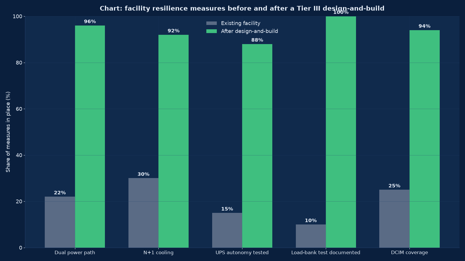
Chart values are an illustrative planning model based on typical UMC engagements and published industry benchmarks. They are not a guarantee of results on any specific project.
A data centre is the only building where the architecture is an electrical argument. Everything else — the slab, the walls, the roof, the floor — exists to protect a chain of decisions about power and heat that were made before anyone drew a rack elevation. Get the chain right and the building lasts fifteen years. Get one link wrong and you will be buying portable chillers and arguing with a landlord in year three, with no way to fix it without moving out.
Data centre design and build at Unified Management Consulting is the work of taking a requirement — so many kilowatts of IT load, so much availability, so many years of growth, so much capital — and turning it into a facility that is designed, procured, installed, tested and handed over with evidence. Not a room with an air conditioner and a rack in it. A facility with a documented power chain from utility intake to rack PDU, cooling that has been proven at full load rather than assumed, structural loading verified by an engineer, fire detection and suppression designed around the fact that the room cannot be flooded with water, and a commissioning record that shows every failure mode was actually simulated while nobody’s production workload was at risk.
We build enterprise data centres and server rooms for organisations that cannot outsource the facility: manufacturers with plant networks, hospital groups with imaging archives and clinical systems that must not leave the estate, media and broadcast operations with live transmission dependencies, financial and insurance back offices, and public-sector bodies with data-residency obligations. We also rebuild the ones that grew without a plan — the server room that started as four racks in a storeroom and is now twenty-two racks drawing 180 kW through a ceiling someone certified for 60 kW in 2009. Both situations need the same discipline. They differ in how much of the design is negotiable, and in a live rebuild almost none of it is.
🏗️ Data Centre Design & Build — Quick Summary
| Component | What We Deliver |
|---|---|
| Requirement and Tier brief | Load forecast in kW and racks, availability target, growth horizon, budget envelope, and the Tier or redundancy topology that follows from them — documented before any drawing is produced. |
| Power architecture | Utility intake, ATS, generator with fuel autonomy, UPS topology and autonomy, STS where needed, distribution to busway and rack PDU, with discrimination studies proving the protection coordination. |
| Cooling plant | Heat-load calculation per hall, cooling topology (perimeter, in-row, rear-door, liquid), redundancy, containment strategy, and the control sequence that decides what happens when a unit fails. |
| Building and structure | Floor loading verification, slab and raised-floor decision, wall and roof build-up, cable pathways, fire compartments, water detection and drainage strategy. |
| Fire, security and life safety | Aspirating smoke detection, gas or water-mist suppression matched to the occupancy, access control zoning, CCTV coverage, and the emergency procedures the operations team will actually use. |
| Structured plant and racks | Rack elevations, busway or whips, containment, fibre and copper pathways, labelling scheme and the permanent-link test records that go with them. |
| DCIM and monitoring | Power and environmental metering at branch level, capacity tracking, alert thresholds tied to the design intent, and the single pane the operations team lives in. |
| Commissioning Levels 1-5 | Factory witness testing, installation verification, functional performance testing, load-bank testing at design load, and integrated systems testing that pulls the plug on purpose. |
| Operating readiness and handover | Runbooks, single-line diagrams that match reality, asset register, maintenance plan, spares holding, and training for the people who inherit the plant. |
| Cost and programme control | Phased capital plan, procurement strategy with lead-time protection, and a risk register that names the items which cannot be changed later. |
What a Design-and-Build Engagement Actually Covers
The phrase “design and build” is used loosely in this market, and the loose usage is why so many facilities arrive incomplete. Some suppliers mean “we will install the equipment you specified”. Some mean “we will produce drawings and let you tender them”. We mean the whole chain, with one party accountable for the outcome rather than for a stage of it: the requirement is established, the design is produced and reviewed, the plant is procured, the installation is supervised, the facility is commissioned at load, and the operations team is handed a building they can run without phoning the contractor.
| Workstream | What we produce | Who signs it off | What breaks if it is skipped |
|---|---|---|---|
| Requirement and Tier brief | Load forecast, availability target, growth horizon, capital envelope, topology decision | CIO or IT director with finance | Everything downstream: you build the wrong size and cannot resize a slab |
| Electrical design | Single-line diagrams, load schedules, discrimination study, UPS and generator sizing, autonomy calculations | Chartered electrical engineer | Nuisance tripping, unprotected faults, UPS autonomy that fails on a real outage |
| Mechanical design | Heat-load calculation, cooling topology, redundancy, control sequence, containment | Chartered mechanical engineer | Hot spots at 60 per cent load, simultaneous cooling failure, condensation on cold aisles |
| Structural and architectural | Floor loading verification, slab or raised floor, pathways, fire compartments, water strategy | Structural engineer and building control | A floor rated below the actual load, and no legal route to fix it |
| Fire and life safety | Detection topology, suppression agent and zoning, emergency procedures, signage | Fire engineer and the local authority | Suppression that damages the plant it saved, or a scheme that never gets signed off |
| Structured plant | Rack elevations, busway, containment, cabling pathways, labelling | Network and infrastructure lead | Untraceable circuits, blocked pathways, a hall that cannot be maintained without an outage |
| DCIM and metering | Meter placement, alert thresholds, capacity model, dashboards | Operations lead | Capacity discovered by failure, no evidence for an audit |
| Commissioning | Level 1-5 test scripts, load-bank programme, integrated systems test record | Independent commissioning agent | A facility that has never been proven at load, so its first real test is a production incident |
| Handover and readiness | As-built documentation, runbooks, asset register, maintenance plan, training | Operations lead and internal audit | Knowledge that leaves with the contractor, and a plant nobody dares to switch |
The sign-off column matters more than the deliverable column. A design-and-build engagement fails quietly when nobody owns the decision: the electrical engineer sizes the UPS, the mechanical engineer sizes the cooling, the contractor orders what fits the budget, and the operations team inherits a facility whose parts were each reasonable and whose whole was never tested against the requirement. We run the workstream table above as a live document with a named owner per row, reviewed weekly, because the alternative is discovering the gap at commissioning when the fix costs ten times as much.
Tier, Redundancy and the Decisions That Cannot Be Reversed Later
Availability language is borrowed from the Uptime Institute’s Tier topology and from TIA-942, and it is worth being precise about what each level buys, because the cost curve is steep and the difference between levels is mostly about maintenance and fault tolerance rather than about how many UPS modules exist. Tier is a topology decision, not a product. Two facilities with identical equipment can sit at different Tiers depending on whether the load can be served while one path is being maintained.
| Level | Power path | Cooling | Concurrently maintainable | Fault tolerant | Indicative annual availability | Who actually needs it |
|---|---|---|---|---|---|---|
| Tier I | Single, no redundancy | Single | No | No | 99.671 per cent (about 28.8 h down per year) | A small branch office where an outage is an inconvenience |
| Tier II | Single path plus redundant components (N+1) | N+1 | No | No | 99.741 per cent (about 22 h per year) | Departmental server rooms with tolerable maintenance windows |
| Tier III | Single path plus redundant components, all maintenance bypassable | N+1 with maintenance isolation | Yes | No | 99.982 per cent (about 1.6 h per year) | Most enterprise data centres: clinical, financial, manufacturing and media estates |
| Tier IV | Two independent paths, both fault tolerant (2N or 2(N+1)) | 2N | Yes | Yes | 99.995 per cent (about 26 min per year) | Live broadcast transmission, payment switching, and anything where downtime is a regulatory event |
The three decisions that are physically irreversible
Most design errors can be corrected later at a price. Three cannot, because they are in the concrete or in the utility agreement, and correcting them means leaving the building.
- Structural capacity. A slab designed for 7.2 kPa will not later support a high-density hall with batteries and a raised floor. Floor loading is verified by a structural engineer against the actual equipment weights — including batteries, which are the heaviest thing in the room and are frequently forgotten in early estimates.
- Utility intake capacity. The transformer and incomer size agreed with the distribution utility caps the facility forever. Upgrading means a new connection application, new switchgear and often a new substation, on the utility’s timetable rather than yours.
- Physical footprint and adjacency. Whether there is space for a second generator, a second chill plant room, or a corridor that allows a rack to be moved without a crane. Growth that has nowhere to go is not growth.
Every design we produce records these three explicitly, with the evidence behind each, so that a client deciding to save money knows precisely which future they are giving up. We have talked clients out of Tier IV more often than into it: a two-path facility is the right answer where an outage is a regulatory or life-safety event, and an expensive way to feel virtuous where it is not.
Power Architecture: From Utility Intake to the Rack PDU
The power chain is the data centre. Everything else supports it. A useful way to design it is to walk the chain from the utility to the socket and ask, at each link, three questions: what does this link protect against, what does it cost in efficiency, and what happens when it fails while the load is live.
| Layer | Purpose | Typical redundancy | Failure mode to design against | Efficiency cost |
|---|---|---|---|---|
| Utility intake and HV switchgear | Bring grid power in at a size that caps nothing | Dual incomers from separate substations where the budget allows | Cable fault or substation outage lasting beyond generator autonomy | None directly |
| Transformer and LV main | Step down and distribute to the plant | N+1 transformers on separate windings | A transformer failure that takes a whole hall | About 1-2 per cent loss |
| Automatic transfer switch | Move load between grid and generator | One per path, with mechanical and electrical interlocks | Failure to transfer, or transferring onto a generator that has not stabilised | None |
| Generator set | Carry the load through a utility outage | N+1 with a common fuel system | Failure to start, fuel contamination, exhausted autonomy | Fuel and maintenance |
| UPS system | Bridge the gap and condition the supply | N+1 modules, or 2N for Tier IV | Battery failure at the worst moment, or autonomy shorter than the design assumed | 3-8 per cent depending on topology and mode |
| Static transfer switch | Give single-cord equipment a second path | Per rack or per row | Both paths sharing an upstream fault, which defeats the purpose | Small |
| Busway or radial distribution | Carry power to rows and racks | Dual busway in Tier III and IV halls | A busway plug fault taking a whole row | Minimal |
| Rack PDU | Meter and switch at the rack | Two per rack, A and B feed | A tripped breaker with no visibility, discovered by an angry application owner | Minimal |
UPS autonomy is arithmetic, not marketing
Autonomy is the time the UPS carries full load on battery while the generator starts and picks up the load — normally eight to fifteen seconds, with ten minutes of margin for a failed start attempt and a retry. A facility designed for fifteen minutes of autonomy assumes the generator will not start; a facility designed for ninety seconds assumes it will. Neither is wrong, but the second is a bet, and the difference in battery plant and floor loading is large enough that it has to be a deliberate decision recorded in the brief. We size autonomy against three numbers: measured generator start-to-load time, the battery’s end-of-life capacity (typically 80 per cent of nameplate), and the ambient temperature of the battery room, because every degree above 20 °C measurably shortens battery life.
Fuel autonomy is the number auditors ask about
Generator fuel is usually specified in hours at full load — twelve, twenty-four, forty-eight — and the real question is whether fuel can be delivered during the event that caused the outage. A forty-eight-hour tank in a city that floods is worth less than a twelve-hour tank with a refuelling contractor whose route does not cross the flood plain. We record the refuelling plan, the access route and the contract, not just the tank size.
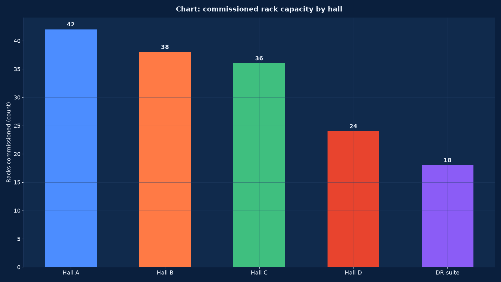
Chart values are an illustrative planning model based on typical UMC engagements and published industry benchmarks. They are not a guarantee of results on any specific project.
Cooling, Containment and the Heat You Have to Move
Cooling design starts with a heat-load calculation, not with a product catalogue. Every kilowatt of IT load becomes a kilowatt of heat, plus the losses from the power chain, plus lighting and people. The calculation is done per hall and per row, because density is never even: the database row draws four times the average and the archive row draws a quarter, and a cooling design based on the average will fail in the hot row within a year of handover.
| Cooling approach | Density it serves well | Retrofit difficulty | What it costs you | Where we specify it |
|---|---|---|---|---|
| Perimeter CRAC or CRAH with a raised floor | 2-5 kW per rack | Low | Floor void leakage, mixing, poor control at high density | Legacy halls and general-purpose server rooms |
| Hot or cold aisle containment with perimeter units | 5-10 kW per rack | Moderate | Doors and ceilings that complicate fire suppression zoning | Most enterprise builds, new and retrofit |
| In-row cooling with containment | 8-20 kW per rack | Moderate to high | Water or refrigerant inside the IT space, and condensate management | Halls with known high density, virtualisation and hyperconverged clusters |
| Rear-door heat exchangers | 10-30 kW per rack | Moderate | Rack door weight, water at the rack, and reduced access | Targeted hot rows inside an otherwise air-cooled hall |
| Direct-to-chip liquid cooling | 30-120 kW per rack | High | Facility water, leak detection, coolant chemistry, and a maintenance team that has been trained | AI and GPU estates where air cannot reach the density at all |
| Immersion | 50 kW and above per tank | Very high | Fluid cost, tank loading, and an operating model most teams do not have | Rarely: only where the workload demands it and the client can staff it |
PUE is an outcome, not a target
Power usage effectiveness is the ratio of total facility power to IT power. A well-run air-cooled enterprise facility in India typically lands between 1.5 and 1.8; containment and economisation pull that toward 1.35; liquid cooling can reach below 1.15. We treat PUE as a consequence of the decisions already made — density, climate, redundancy, and how much the client is willing to spend on controls — and we report the design PUE with the assumptions attached. A quoted PUE with no stated ambient condition and no load profile is not a number, it is advertising.
Simultaneous failure is the test that matters
N+1 cooling is not redundancy if the control sequence lets the remaining units idle while the failed unit’s load goes unserved. We write and then test the sequence: on loss of a cooling unit, the standby unit starts, the containment dampers behave as designed, non-critical load sheds if the hall is above its thermal limit, and the alert reaches a human being with a runbook reference. That test is part of integrated systems testing, and it is performed under load, with the hall at design temperature, not on an empty floor with the doors open.
The Building Itself: Structure, Fire, Water and Access
Facilities fail in ways that have nothing to do with IT. Water gets in. A fire suppression discharge damages the plant it saved. A door is too narrow for the UPS. A floor is not rated for the batteries. Each of these is cheap to design around and ruinous to retrofit, so they are settled in the architectural stage with an engineer’s evidence attached.
| Building consideration | What we verify | Evidence produced | Consequence of getting it wrong |
|---|---|---|---|
| Floor loading | Actual equipment weights including batteries, raised floor pedestals and point loads | Structural engineer’s calculation and sign-off | A hall that cannot legally hold the plant installed in it |
| Slab versus raised floor | Density, cabling volume, airflow strategy, future flexibility | Decision record with the cooling design attached | A floor void that becomes a rubbish dump, or a slab hall with no way to route power |
| Ceiling height and clearances | Rack height plus busway, containment and lifting access | Section drawings and a rack-moving route | Racks that cannot be brought in, or containment that cannot be installed |
| Fire compartments and suppression | Occupancy, agent selection, door and damper interfaces, discharge zoning | Fire engineer’s design and authority sign-off | A suppression system that never passes inspection, or one that floods adjacent rooms |
| Water detection and drainage | Leak detection rope under cooling and around the hall, drainage paths, no wet services overhead | Detection zoning plan and alarm matrix | A leak discovered by a short circuit rather than by a sensor |
| Physical security zoning | Perimeter, building, hall, rack-level access, visitor escort routes | Access control zoning diagram with badge groups | A single badge that opens everything, and an audit finding that cannot be closed |
| Environmental conditions | Temperature and humidity set points against ASHRAE recommended ranges, and the alarm band around them | Set-point schedule with sensor placement plan | Condensation on cold surfaces, or static risk from over-dry air |
Two of these are routinely underestimated. Batteries are heavy: a UPS room can impose point loads that exceed a floor designed for office occupancy, and the calculation must use end-of-life weights plus the rack’s own mass. And doors are narrow: a modular UPS or a generator enclosure that cannot pass through the loading route is a crane job, a wall opening, or a redesign — none of which anyone wants to discover on delivery day. We walk the delivery route with the equipment schedule in hand and record the tightest dimension.
Structured Plant, Racks and the Hall Nobody Can Maintain
Inside the hall, the design has to survive contact with maintenance. A rack elevation is not a picture of full racks; it is a plan that leaves space for airflow, for cable bend radii, for a technician’s hands, and for the rack that has not been ordered yet. We produce elevations per hall with power feed assignment, U positions reserved for network and patching, weight distribution checked against the floor, and the A and B feed labelled so that a single-cord device cannot accidentally be given both feeds from one busway.
| Hall element | Design rule we apply | Why it exists |
|---|---|---|
| Rack spacing | Cold aisle at least 1.2 m clear, hot aisle at least 0.9 m, plus the containment door swing | A technician who cannot open a door cannot maintain the rack behind it |
| Power feed assignment | A and B feeds from separate upstream paths, verified against the single-line diagram | Two feeds from one busway is one feed with extra steps |
| Busway and whips | Plug positions matched to the rack elevation, with spare capacity at the end of each run | Growth that needs a new busway run means an outage |
| Cable pathways | Overhead fibre and copper trays separated, with fill ratios below 60 per cent | A full tray cannot be added to, and mixed pathways make faults hard to trace |
| Labelling | Circuit, rack, U position and both ends of every link labelled to one scheme | Unlabelled plant turns every maintenance window into an investigation |
| Blanking and airflow | Blanking panels specified as part of the build, not as a later housekeeping task | Recirculation through empty U spaces defeats the containment design |
| Earthing and bonding | Rack bonding to the hall earth bar, with measured resistance | Both a safety requirement and the defence against the fault nobody can reproduce |
This workstream is where the facility meets the network, and it is deliberately coordinated with the structured cabling and LAN/WAN design that runs alongside it rather than after it. Pathways decided by the builder and then re-decided by the network team produce exactly the spaghetti that makes a hall unmaintainable.
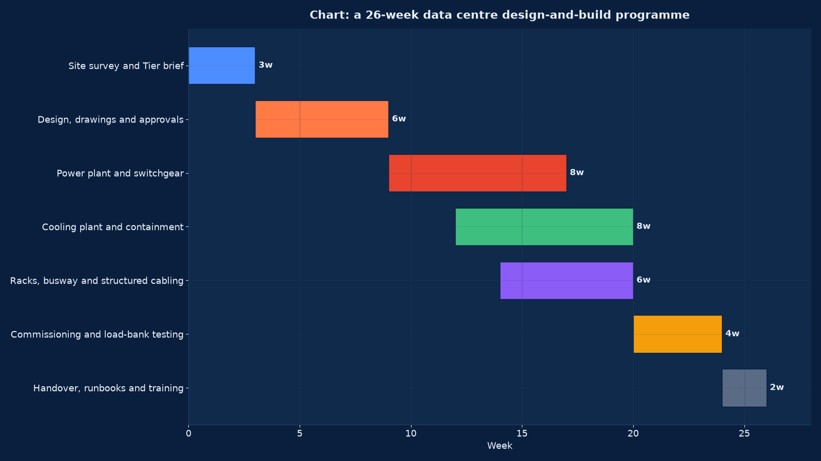
Chart values are an illustrative planning model based on typical UMC engagements and published industry benchmarks. They are not a guarantee of results on any specific project.
Commissioning: The Only Stage That Proves the Design
Commissioning is where a designed facility becomes a proven one, and it is the stage most often compressed to save a fortnight. It follows a recognised progression — Level 1 design review, Level 2 equipment and installation verification, Level 3 pre-functional and functional testing, Level 4 load testing, Level 5 integrated systems testing — and each level assumes the previous one passed. Skipping to Level 5 with unverified installations produces a test result nobody can interpret.
| Level | What happens | Who performs it | Evidence produced |
|---|---|---|---|
| Level 1 — design review | Drawings, calculations and specifications checked against the Tier brief and each other | Commissioning agent with the design engineers | Review log with comments closed out |
| Level 2 — equipment verification | Delivery inspection, factory test certificates, installation checks against the drawings | Commissioning agent and installer | Inspection records and factory witness test certificates |
| Level 3 — functional testing | Each system tested individually: UPS transfer, generator start and load pickup, cooling unit failover, alarm paths | Commissioning agent | Signed test scripts per system |
| Level 4 — load testing | Load banks simulate design IT load; power and cooling proven at full capacity, thermal mapping across the hall | Commissioning agent with load-bank operator | Load-test records and thermal maps |
| Level 5 — integrated systems testing | Failure scenarios performed on the whole facility: utility loss, UPS module failure, cooling unit failure, simultaneous events | Independent commissioning agent | IST scripts, results and a punch list closed before handover |
Load-bank testing is not optional and not a formality
A generator that starts on a no-load test tells you almost nothing. It has to accept the design load in steps, hold it, and shed it without overspeed or wet-stacking; a UPS has to carry load on battery for its full autonomy period with the actual battery string, not the one on the datasheet; a cooling plant has to hold a hall at set point with the full heat load present, including the hot rows. We run load banks to design load, in the sequence written into the test script, with results recorded per step. Where the facility will hold production equipment later, the load test happens before that equipment arrives — which is the entire reason commissioning has a date in the programme rather than a footnote.
Integrated systems testing pulls the plug on purpose
The IST script is written from the failure modes in the design, not from a template. Utility power is removed and the facility is watched through generator start, transfer, and return. A UPS module is failed while loaded. A cooling unit is killed and the standby is proved to pick up with the hall at temperature. Two events are combined where the design claims fault tolerance. Every step has an expected outcome, an observed outcome and a signature. Where the observed outcome differs, the item goes on a punch list and the facility does not go live until it is closed — which is why the commissioning agent must be independent of the installer. We will not certify our own work and neither should anyone else.
DCIM, Metering and Knowing Your Capacity Before It Runs Out
A facility without branch-level metering discovers its capacity limits by tripping a breaker. DCIM is not a dashboard purchase; it is the metering design that makes a dashboard possible. We specify meter placement at incomer, UPS output, busway and rack PDU, environmental sensors per cold aisle and per hot aisle, leak detection zoning, and alert thresholds derived from the design intent rather than from vendor defaults — a threshold set at 80 per cent of a breaker rating that was itself chosen for a load forecast from 2019 is a threshold that tells you nothing.
| What we meter | Why | The question it answers |
|---|---|---|
| Incomer and main distribution | Total facility power, and the split between IT and plant | What is our real PUE this month, and is it drifting? |
| UPS input, output and battery | Load per module, autonomy remaining, battery health | How long do we actually have, and when do the batteries need replacing? |
| Generator | Start success, run hours, fuel level, exercise results | Will it start on the night it matters? |
| Busway and rack PDU | Load per rack and per phase, with imbalance alerts | Which racks have capacity, and which are one device away from a trip? |
| Environmental sensors | Cold-aisle and hot-aisle temperature, humidity, differential pressure | Where is the hot spot forming, and is containment leaking? |
| Leak detection | Water under cooling plant and around the hall perimeter | Is there water in the room before there is water in a rack? |
| Access control and CCTV | Who entered which zone and when | Can we close an audit finding about physical access? |
Capacity reporting is the operational payoff. Once the meters exist, capacity is a weekly number in three units — kilowatts, rack units and floor area — and the first of the three to exhaust decides when the facility is full. Most organisations discover too late that it was power rather than space, which is why we report all three from day one and forecast each against the growth horizon in the brief.
How This Differs From Our Broad Computing and Data Centre Page
Our Computing, Server, Storage and Data Centre Engineering page covers the estate as a whole: servers, storage, virtualisation and the engineering that keeps an existing facility productive. This page is narrower and deeper, and the difference matters when you are buying. If your facility exists and your question is how to run, consolidate or modernise what is in it, that page is the right starting point. If your question is how to design, build, extend, relocate or certify the facility itself — a new hall, a Tier reclassification, a power chain that cannot carry the load you now have, a move to a new building with production workloads that cannot stop — then the engagement described here is the one you need, and it is delivered with chartered engineers, an independent commissioning agent and a load-tested handover rather than a set of drawings.
| Question you are asking | Right starting point | What that engagement produces |
|---|---|---|
| “Our servers and storage are ageing — what should the estate look like in three years?” | Computing, Server, Storage and Data Centre Engineering | An estate roadmap: refresh, consolidation, virtualisation and the capacity plan behind it |
| “We need a new hall, a new building, or a facility that can be certified at a higher Tier” | This page | Full design and build with chartered engineering sign-off and Level 1-5 commissioning |
| “Our backups and recovery cannot meet the RTO the business has agreed” | Backup, Disaster Recovery & Business Continuity Services | A recovery architecture and the test regime that proves it, which often changes what the facility must provide |
| “The network inside and between our sites is the constraint” | Routing, Switching, Firewall and Network Engineering | The LAN, WAN and security design the facility has to house and cool |
| “We want the plant run for us once it is built” | Managed IT Infrastructure & IT AMC Services | A managed service with published SLAs against the facility we handed over |
Those engagements are frequently combined, and where they are, one team holds the requirement. A design-and-build that hands over to a managed service we did not write the runbooks for is a common and avoidable failure.
What We Need From You Before Design Starts
A design produced without these inputs is a guess with drawings attached. We collect them in the first two weeks and treat them as a contractual input, because every one of them changes the answer.
| Input | Why it decides the design | Who provides it |
|---|---|---|
| Current and forecast IT load in kW | Sizes the entire power chain and the cooling plant | IT operations, from measured PDU data where it exists |
| Rack count and density profile | Decides containment, cooling topology and floor loading | IT operations with the application owners |
| Availability requirement and the cost of an hour down | Decides Tier, and therefore capital | The business, not IT |
| Growth horizon in years | Decides how much headroom is bought now versus later | Finance with the business plan |
| Regulatory and data-residency obligations | Can rule out colocation or public cloud for specific workloads | Compliance or legal |
| Existing building constraints | Floor loading, ceiling height, utility intake, delivery route | Facilities or the landlord, with an engineer’s survey |
| Maintenance window reality | Decides whether concurrent maintainability is achievable or theoretical | Operations |
| Who runs it after handover | Decides automation level, spares holding and the training package | IT leadership |
Where measured PDU data does not exist — which is common, and is itself a finding — we meter for two to four weeks before the load forecast is signed off. A forecast built on nameplate ratings typically overstates load by 40 to 60 per cent, because almost nothing runs at nameplate, and an overstated load buys an oversized facility that then runs inefficiently for its whole life.
Cost, Phasing and the False Economy of Skipping Stages
Facility capital splits in a fairly stable pattern across enterprise builds, and knowing where the money goes is what makes a phased plan possible rather than aspirational. The shares below are indicative of the builds we plan, not a quotation.
| Cost driver | Indicative share of facility capital | Where it is commonly wasted | How we protect it |
|---|---|---|---|
| Power plant: switchgear, UPS, batteries, generator | 30-38 per cent | Oversizing from nameplate load; buying autonomy nobody will maintain | Measured load forecast, autonomy decided as a recorded risk |
| Cooling plant and containment | 18-24 per cent | Cooling to the average rather than the hot row | Per-row heat-load calculation, containment specified with the cooling |
| Building works and structure | 14-20 per cent | Discovering floor loading after installation | Structural verification before procurement |
| Structured plant, racks and busway | 8-12 per cent | Cheap racks and no blanking, re-cut later | Elevations and airflow rules issued as part of the design |
| Fire, security and life safety | 6-10 per cent | Suppression selected before the occupancy is fixed | Fire engineer engaged at concept stage |
| DCIM, metering and monitoring | 3-6 per cent | Deferred as optional, then retrofitted at triple the cost | Meter placement designed with the electrical design |
| Commissioning and handover | 3-6 per cent | Compressed to save a fortnight | Independent agent appointed at design stage, with Level 4 load testing dated in the programme |
Phasing without stranding
Most clients cannot fund the whole facility in one year, and most phased builds strand capacity: the second phase arrives to find the first phase has consumed the pathways, the floor loading or the utility headroom it needed. A phaseable design decides upfront which elements must be bought whole — utility intake, structural capacity, main distribution, pathways — and which can be added later, such as UPS modules, cooling units and racks. That split is a design decision with a capital consequence, and it is made explicitly rather than discovered during the second phase’s site survey.
Risk Register We Run on Every Build
The register below is the short version of the one we maintain per project. Each risk has an early signal, because a risk without a signal is only discovered when it has already become an incident.
| Risk | Early signal | Mitigation we apply |
|---|---|---|
| Lead time on generator, UPS or chill plant exceeds the programme | Quoted delivery slipping at tender stage | Early procurement of long-lead items, with deposit and factory slot secured before design is frozen |
| Floor loading inadequate for the intended density | Structural survey deferred, or battery weights missing from the schedule | Verification before procurement, and a density plan that fits the verified loading |
| Utility intake cannot serve the forecast load | Utility connection enquiry unanswered, or a verbal assurance | Written connection offer obtained during concept design |
| Cooling proven only at part load | Load testing scheduled after production equipment arrives | Level 4 load-bank testing dated before any production load, with thermal mapping |
| Commissioning agent not independent | Installer offering to self-certify | Independent agent appointed at design stage |
| Documentation delivered as-built in name only | Handover pack arriving without markup history | Progressive documentation with redlines reviewed at each level, not at handover |
| Operations team not trained before go-live | Training scheduled as a half-day in the final week | Runbook-led training during Level 5 testing, so the team watches the failures happen |
| Scope creep from business units adding racks mid-build | Rack requests arriving outside the change process | Change control tied to the capacity model, with power and cooling impact assessed per request |
Two of these deserve emphasis. The independence of the commissioning agent is not a procurement nicety; it is the difference between a test record and a warranty claim. And documentation delivered at handover rather than progressively is always wrong, because nobody reconstructs six months of markups accurately from memory in the final week of a project.
Evidence From Our Work
Facility work is rarely publishable in detail — the buildings are client-confidential and the single-line diagrams more so — but the surrounding infrastructure engagements are, and they show the same discipline applied at the scale most enterprises actually operate at: a server room, a hall, a handful of racks and a chain of decisions about power, cooling and monitoring that had to survive an audit.
- Global Hospitals — Case Study — a multi-location healthcare network’s server room built out with high-performance switching and a routing architecture, delivered over a six-to-nine month implementation with twenty-four months of support behind it. Clinical estates cannot tolerate a facility designed to the average load.
- IT Infrastructure Management for an IT Company — Case Study — twenty-four-by-seven monitoring, remote and on-site support, preventive maintenance and security management for a media and broadcasting company under a twenty-four month renewable contract. Broadcast is the clearest case for commissioning: the load is live and the outage is on air.
- Marriott Hotel Hyderabad — Case Study — twenty-four-by-seven managed services, monitoring and maintenance across multi-property operations, where the plant sits in buildings nobody designed for it.
- Enterprise Computer Networks: Trends, Operations, and Careers — the operational context a facility has to serve, including the monitoring and handover discipline that decides whether a build stays healthy.
- AI Infrastructure Capacity and Capital Intensity: What the Nscale Story Reveals — why density is rising fast enough that cooling topology, not floor area, now decides when a hall is full.
- Tech Stack Consolidation: The Business Case for Unified Systems — the consolidation argument that usually triggers a facility rebuild, and the load forecast error it introduces if nobody re-measures.
- our Technology archive — further writing on infrastructure, operations and the engineering decisions behind them.
Frequently Asked Questions About Data Centre Design and Build
Do we need Tier III, or is that an expensive habit?
Tier III buys concurrent maintainability: you can service any component while the load keeps running. That is worth having where a maintenance window cannot be scheduled without business impact — clinical systems, payment processing, live broadcast, anything on a published SLA. It is not worth having where a four-hour Saturday window is genuinely available. Tier IV adds fault tolerance through two independent paths and is rarely justified outside regulated switching or transmission. We start from the cost of an hour of downtime and work backwards, and we have talked clients out of Tier IV more often than into it.
How long does a build take, and what decides the programme?
A mid-size enterprise hall typically runs twenty to thirty weeks from brief to handover, and a full facility rebuild in a live building runs longer. The programme is decided by long-lead procurement, not by installation labour: generators, UPS modules, switchgear and chill plant commonly carry twelve to twenty-six week lead times. That is why power and cooling procurement run in parallel in our programme, and why freezing the design late is the single most reliable way to lose two months.
Can you design and build while our production systems stay live?
Yes, and most of our work is exactly that. It requires a migration sequence designed before any installation starts, temporary power and cooling for the transition, and maintenance windows agreed per workload rather than globally. The constraint is never the building; it is the sequence. Where a hall cannot be worked live, we plan a phased move with the recovery architecture tested before the first workload shifts.
What does floor loading have to do with my IT project?
More than anything else in the building. Batteries and high-density racks impose point loads that exceed what most office or storeroom floors were designed for, and a floor is not strengthened after the plant arrives. We verify loading with a structural engineer against actual weights — including end-of-life battery mass, which is frequently missing from early schedules — and the verification happens before procurement, because it can change what you are allowed to buy.
How do we know the cooling design will actually hold?
By testing it under load before production arrives. Level 4 commissioning runs load banks to design IT load and thermally maps the hall, which reveals the hot rows that a design calculation averages away. We also kill a cooling unit deliberately during Level 5 integrated testing, with the hall at temperature, and watch the standby pick up and the control sequence behave. A cooling design that has only ever run at 30 per cent load has not been tested.
What is PUE and should we commit to a number?
Power usage effectiveness is total facility power divided by IT power, so lower is better. For an air-cooled enterprise facility in Indian conditions, 1.5 to 1.8 is typical; containment and economisation pull toward 1.35; liquid cooling can go below 1.15. We report a design PUE with its assumptions — ambient condition, load profile, redundancy mode — and we do not recommend committing contractually to a number whose assumptions you do not control. A PUE quoted without an ambient temperature is not meaningful.
Do we need DCIM on day one, or can it wait?
The metering cannot wait; the dashboard can. Meter placement is an electrical design decision, and retrofitting branch-level metering later means working on live distribution. We specify meters at incomer, UPS output, busway and rack PDU, plus environmental and leak detection zoning, during design. The software layer can be phased, but the measurement points cannot.
What happens if our growth forecast turns out to be wrong?
It usually is, in one direction or the other, which is why we phase deliberately. Elements that must be bought whole — utility intake, structural capacity, main distribution, pathways — are sized to the growth horizon in the brief. Elements that can be added — UPS modules, cooling units, racks, busway plugs — are deferred with the space and headroom reserved for them. Where no measured load data exists we meter for two to four weeks before signing off the forecast, because nameplate-based forecasts commonly overstate load by 40 to 60 per cent.
Who commissions the facility if you build it?
An independent commissioning agent, not us. The value of Level 5 integrated systems testing is that the party writing the test script has no commercial interest in the result. We appoint the agent at design stage so the test scripts are written against the design intent, and handover is conditional on the punch list being closed rather than on the plant being installed.
Is colocation or a hyperscale cloud a better answer than building?
Frequently, and we say so when it is true. Building is the right answer where data residency or latency rules out alternatives, where the workload profile is steady enough that capital beats operating cost over the horizon, or where the density you need is not available commercially at a sensible price. Where none of those hold, a colocation or cloud-first strategy with a small on-premises edge is usually cheaper and faster. That assessment is part of the requirement stage, before anyone draws anything.
What documentation do we get at handover?
As-built single-line diagrams that match the installed plant, rack elevations, cooling and control sequences, commissioning records for all five levels including load-bank and IST results, thermal maps, the asset register, maintenance plan and spares holding, runbooks per failure mode, and the training record for the team that inherits it. Documentation is produced progressively with redlines reviewed at each level, because a pack assembled in the final week is always inaccurate.
Can you help with a facility we inherited rather than built?
That is a large share of our work. We survey the installed plant against its documented design, measure the actual load and cooling performance, verify floor loading and utility headroom, and produce a condition and risk assessment with a remediation plan. The most common findings are a power chain that cannot carry the current load, cooling designed to an average that no longer exists, and no metering — in that order.
Arrange a Facility Review Before You Commit Capital
A design-and-build decision is mostly made before the drawings start: in the load forecast, the Tier decision, the structural verification and the utility conversation. If any of those four is unsettled, the capital you commit is a bet rather than a plan. We will survey what you have, measure what it actually carries, and tell you plainly whether you should build, extend, reclassify, relocate or leave it alone — including when the honest answer is that colocation or cloud is cheaper than the hall you were about to fund.
Contact Unified Management Consulting to arrange a confidential first conversation.
Related Services
Facility work rarely stands alone. These are the engagements it most often runs alongside:
- Computing, Server, Storage and Data Centre Engineering — the estate the facility exists to house, and the right starting point when the building is fine and the question is what runs in it.
- Backup, Disaster Recovery & Business Continuity Services — the recovery architecture that decides what the second site must provide, and frequently changes the primary facility’s brief.
- Routing, Switching, Firewall and Network Engineering — the LAN, WAN and security design that the hall has to house, cool and power.
- Managed IT Infrastructure & IT AMC Services — running the plant after handover against published SLAs, with the runbooks we wrote during commissioning.
- Enterprise Systems Integration & Tech-Stack Consolidation — the consolidation that usually justifies the build, and the load forecast error it introduces if nobody re-measures.
- IT Audit, Compliance & ISO 27001 / SOC 2 Readiness — the physical and environmental controls an auditor will test, and the evidence a commissioned facility can actually produce.
- Cloud-Native Application Modernisation Services — for the workloads that should leave the facility rather than be housed in it.
- Backup & Disaster Recovery Infrastructure — backup estates, immutability, replication, documented RPO and RTO and the restore tests that prove them
- Hyperconverged Infrastructure (HCI) Services — hyperconverged clusters where compute, storage and availability are one licensing and one failure domain
- Server Virtualisation (VMware / Hyper-V) Services — VMware and Hyper-V clusters, host sizing, cluster policy and the runbook that survives a host failure
- Storage & SAN Engineering Services — SAN and NAS design, tiering, replication and the recovery evidence behind the capacity plan